Building the X-Carve: A Journal of Our Experiences
Day 1: 3 1/2 Hours
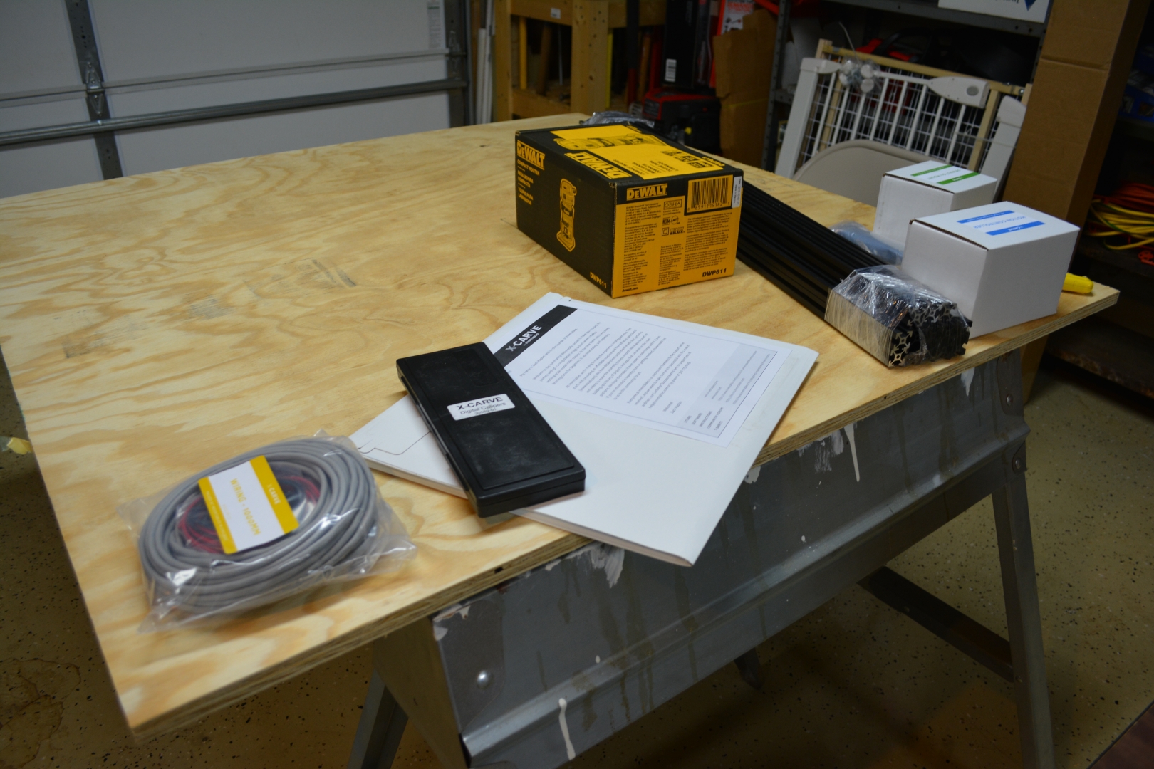
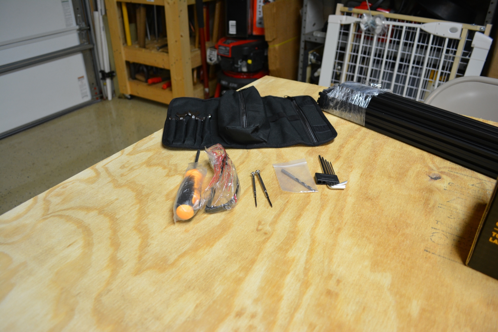
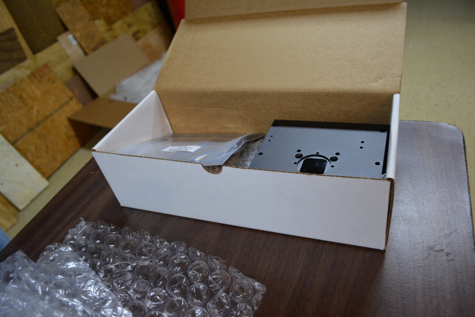
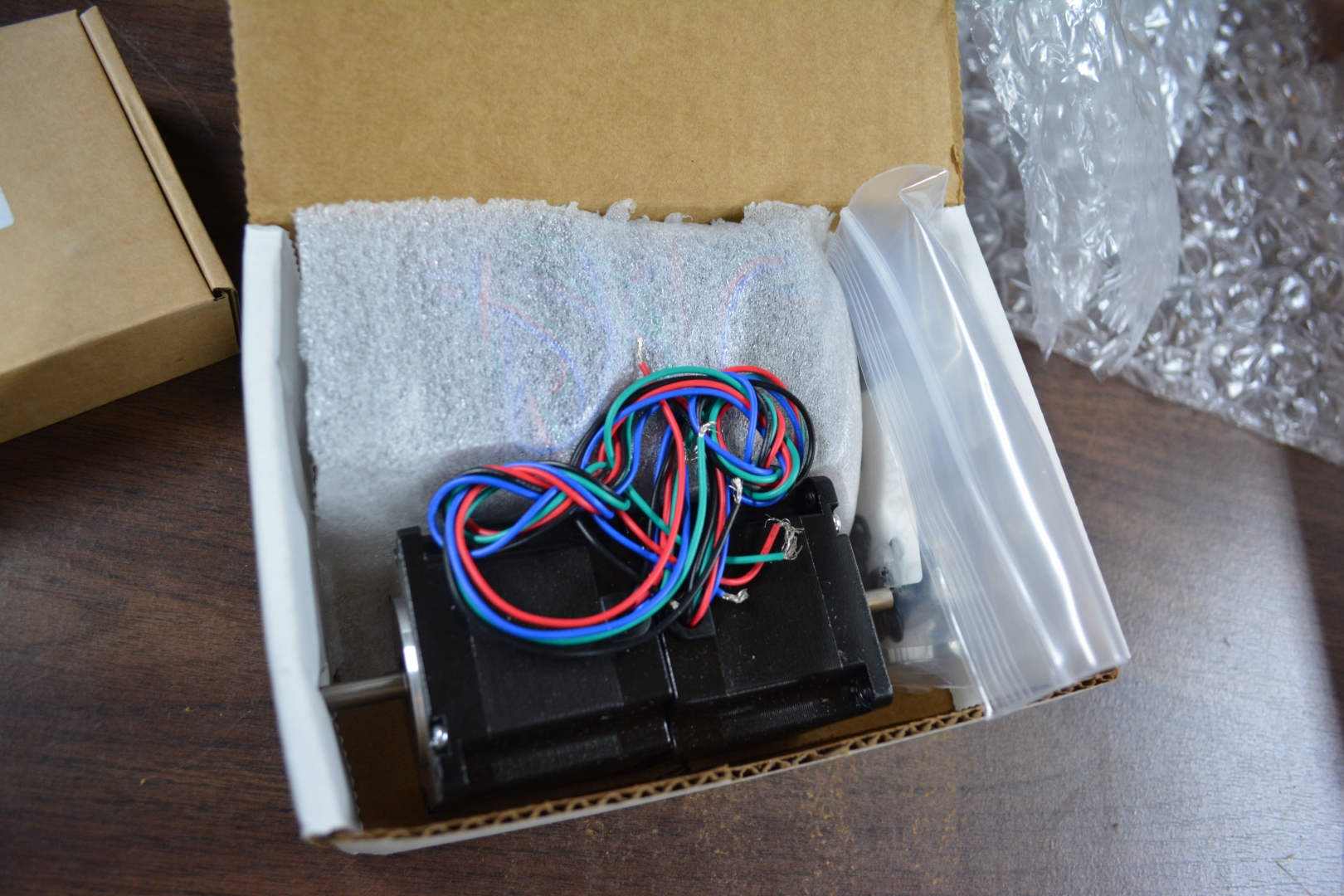
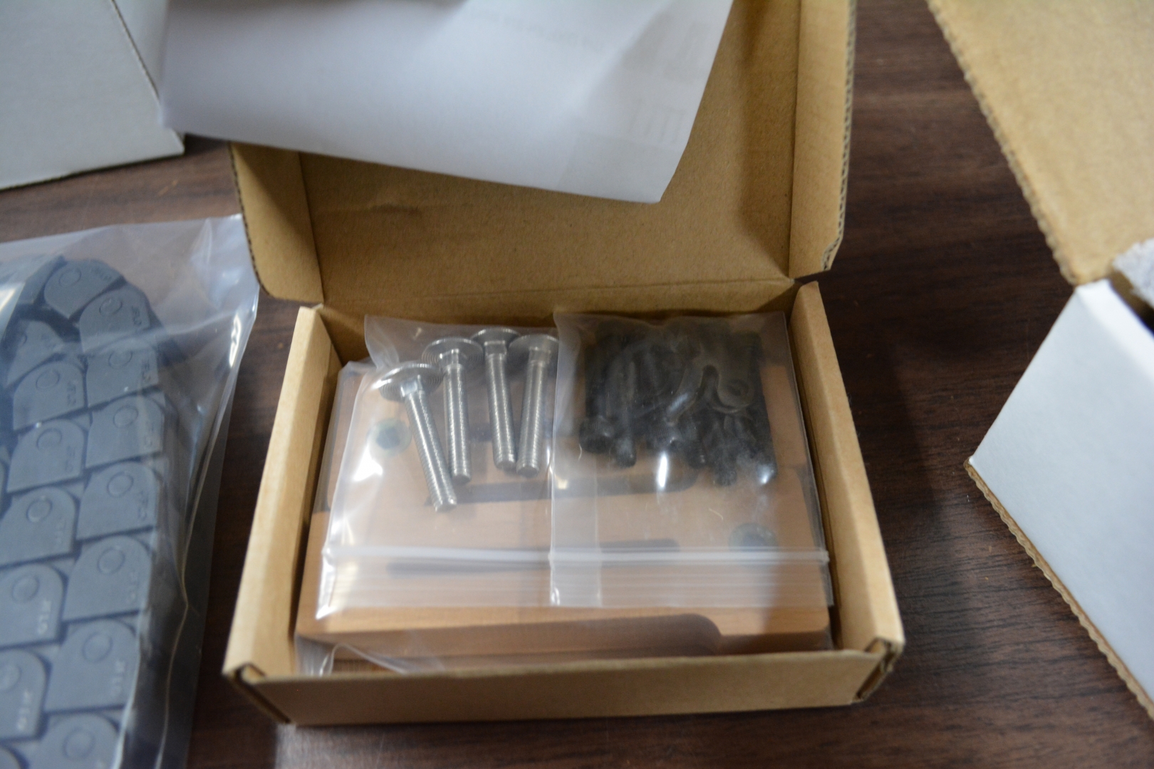
Unpacking - 1/2 Hour:
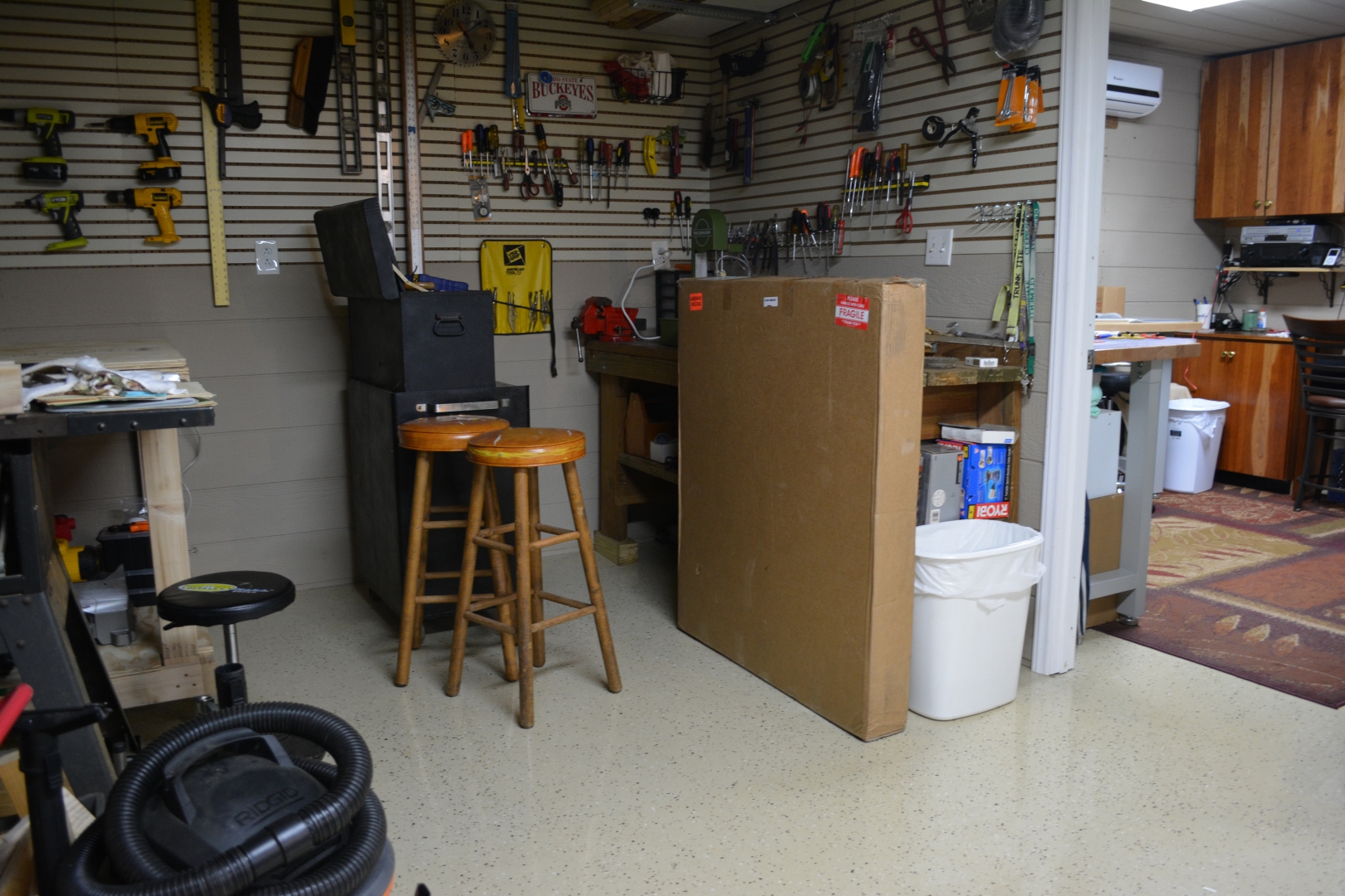
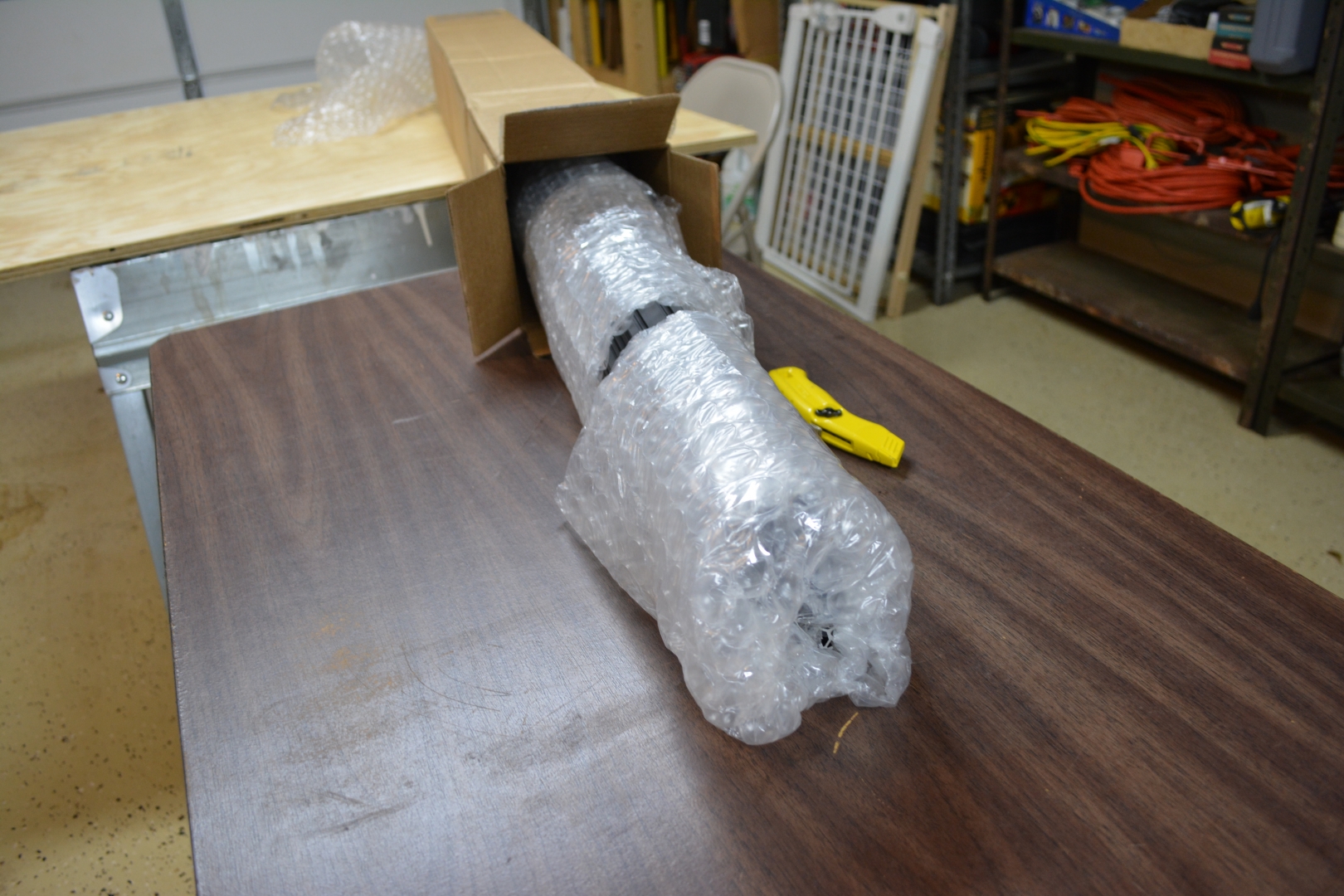
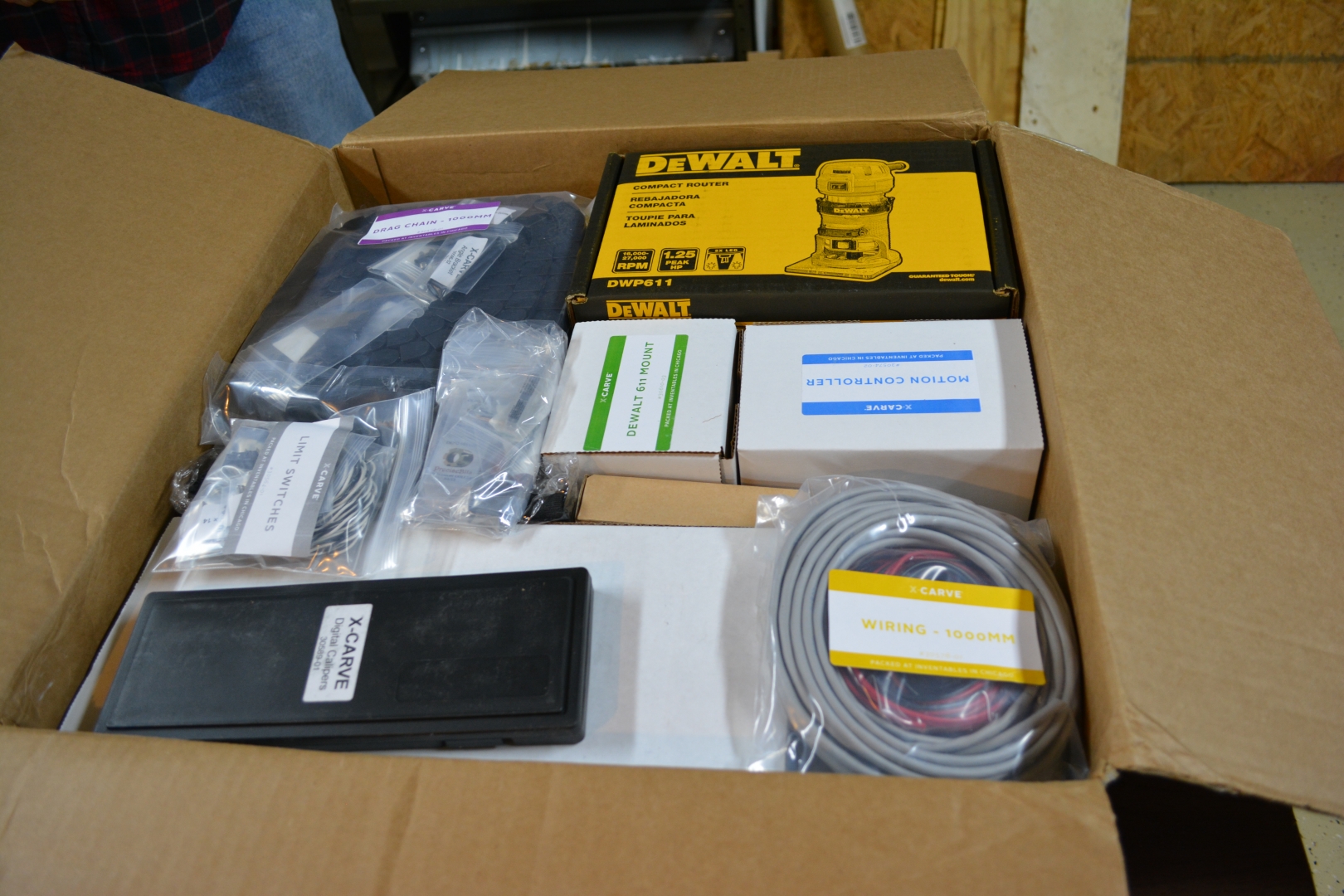
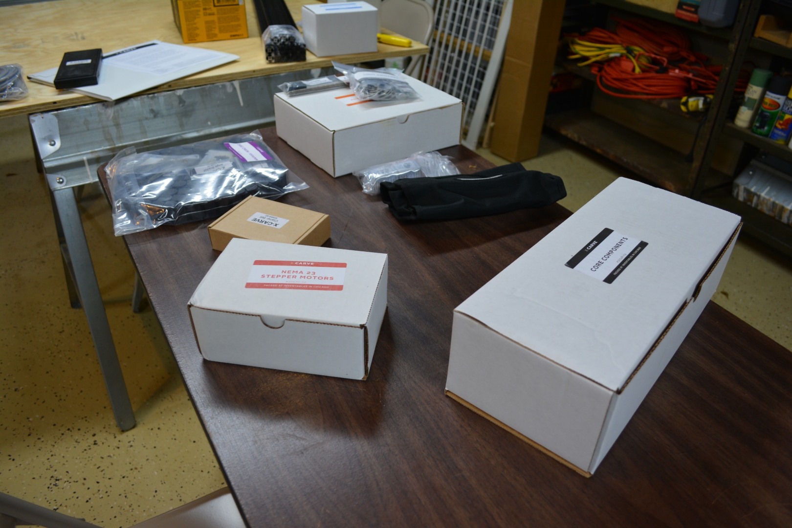
Everything arrived very neatly packed, and basically on time, there was a minor delay on UPS’s end, but Paul over at Inventables worked with us to figure it out. Every type of component came in its own bag that was clearly labeled, but, as a side effect, this creates a lot of wasted plastic. I would highly recommend getting the toolkit, mainly because you are guaranteed to have tools that fit and it is a good backup just in case.


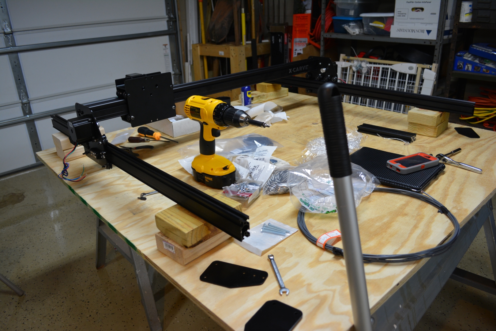
The X-Carriage - 2 Hours:
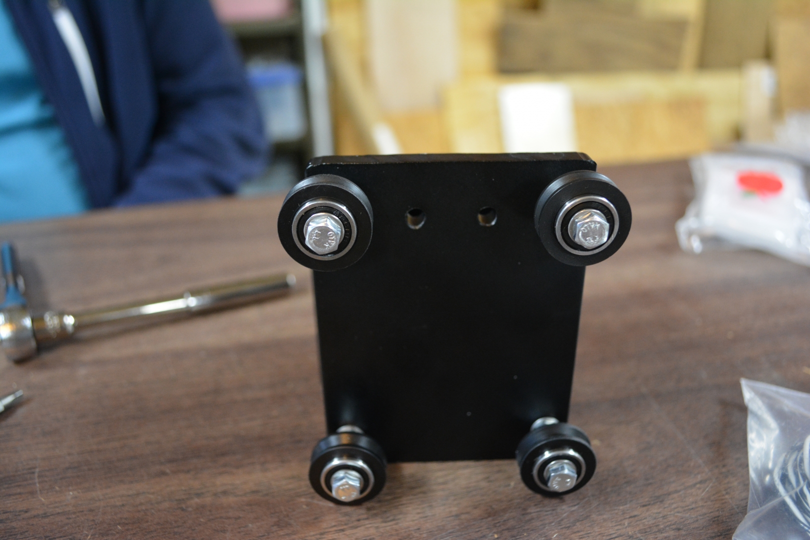
I will say right off the bat, the instruction guide’s pictures are not that great. They are at weird angles, show things that we have not even neared starting, and it is very difficult to discern how things are to be assembled. The videos are even harder to understand, which led to an hour of fiddling with the V-Wheels to arrange them so a maker slide could actually slide through them. Since I am already talking about the V-Wheels, I have encountered another issue. The instructions do not mention at all how tight the V-Wheels need to be to the MakerSlide and how easily it needs to slide along it. We were able to put on the Smooth Idlers, the terminal blocks, and the NEMA 23 motors without incident and those instructions were very clear on how they were put together. We decided to hold off on putting on the Drag Chains because the connectors were already attached and, while trying to remove it like the instructions said, it felt like they were going to break. We also held off on putting on the Limit switches because they look and feel very fragile, we did not want to break them before even starting the machine and we want to pick up some shielded wire for the limit switches.


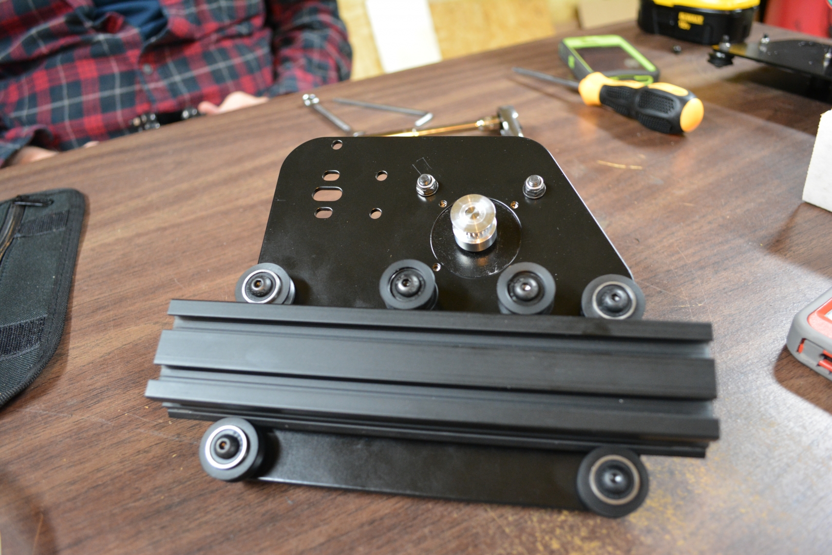
The Y-Plates: Part 1 - 1 Hour:
After the learning on how to assemble the V-Wheels correctly, we were able to assemble the Y-Plates without any major issues. We did run into an issue where one of the pulleys would not smoothly slide onto the NEMA motors, so we had to tap it with a screwdriver handle to get it into place. Again we skipped the drag chains and the limit switches. We were not able to get the terminal block on tonight because we ran out of time. As I was writing this post, I realized we might have forgotten to mirror one of the Y-Plates, so we need to fix that tomorrow.
Day 2: 4 Hours
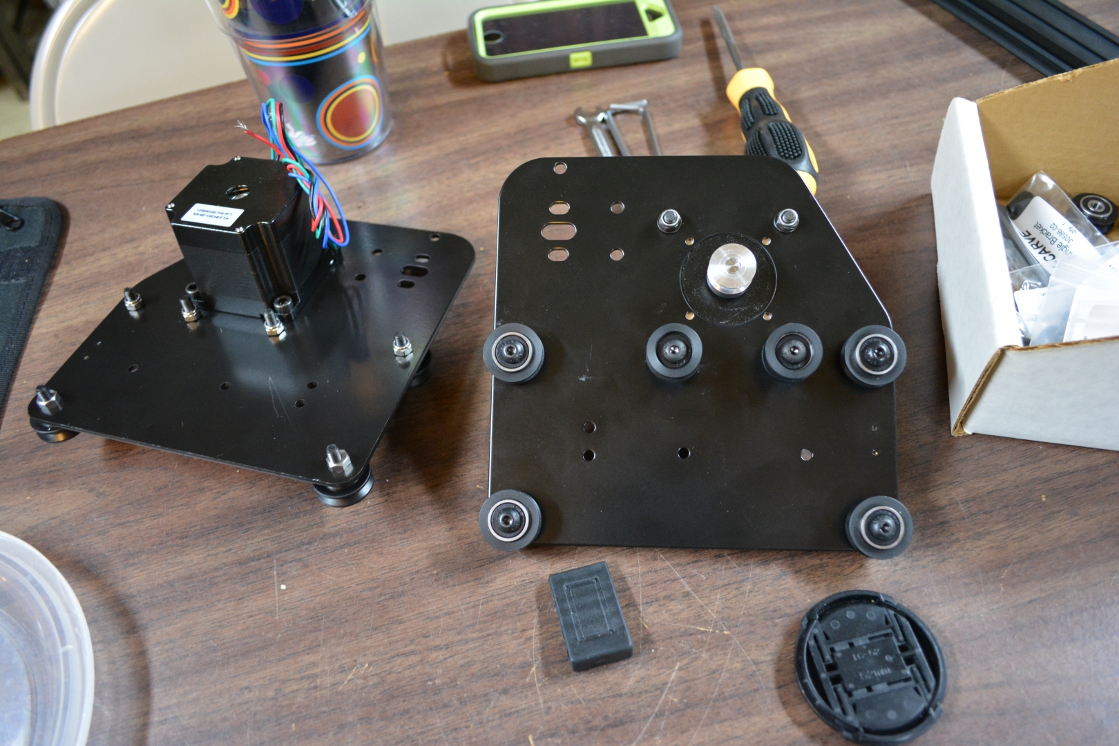
The Y-Plates: Part 2 - 2 Hours:
We did forget to mirror the plates and we had the motor cabling facing the top instead of the bottom. Fixing that took up most of our night. After we fixed our mistakes, assembling the Gantry.
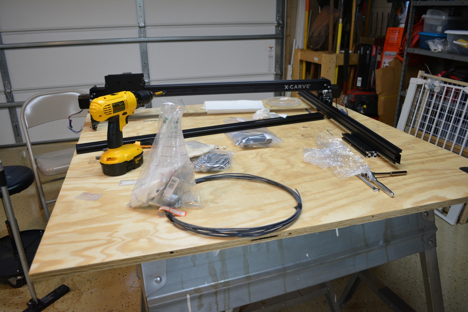
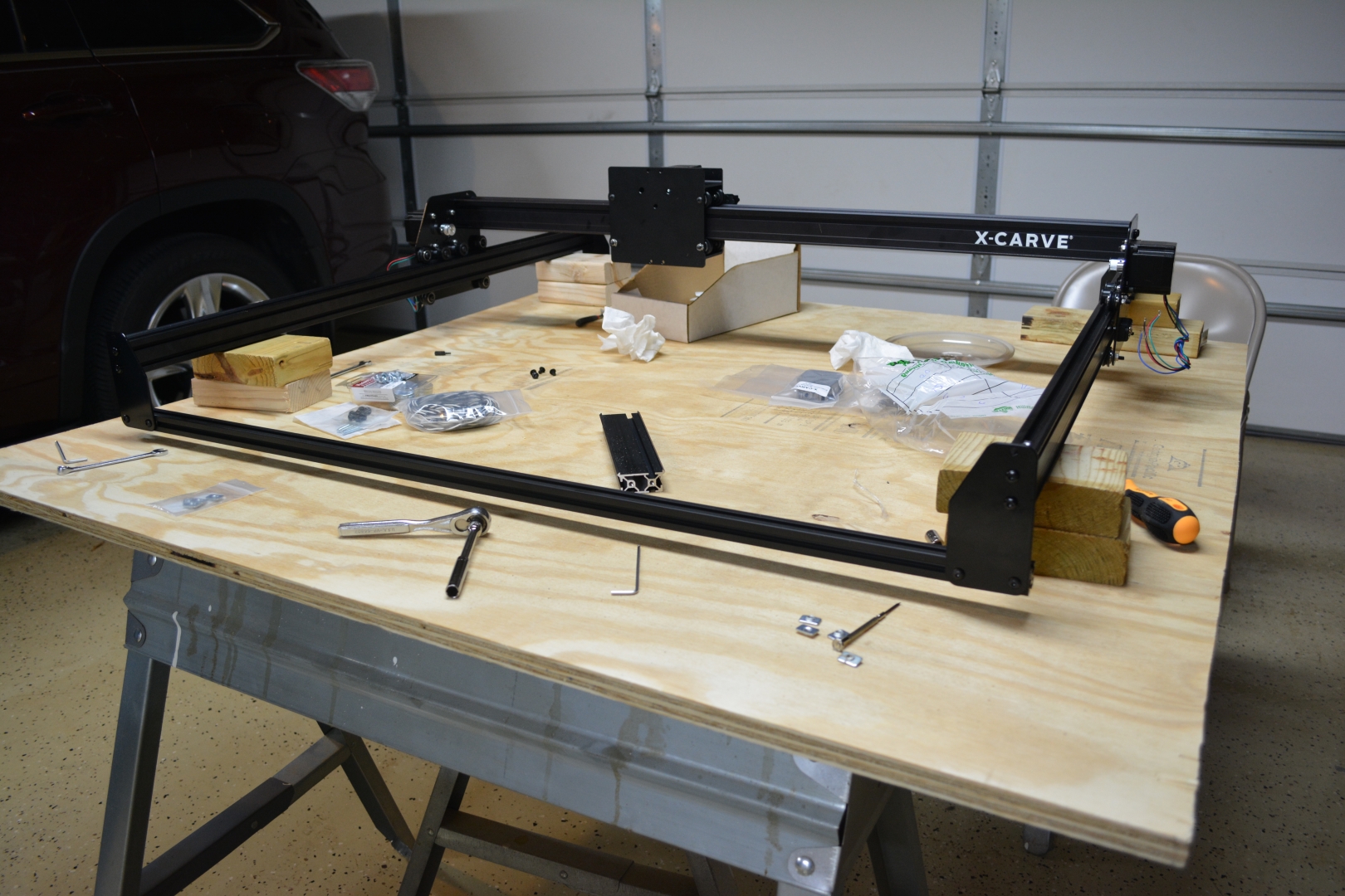
The Gantry - 1 Hour:
The gantry, was fairly straight forward, it just took a long time to build because we had to slowly put in all the self tapping screws. After we assembled everything, we realized that we would not be able to attach the limit switches with the Gantry Assembled.

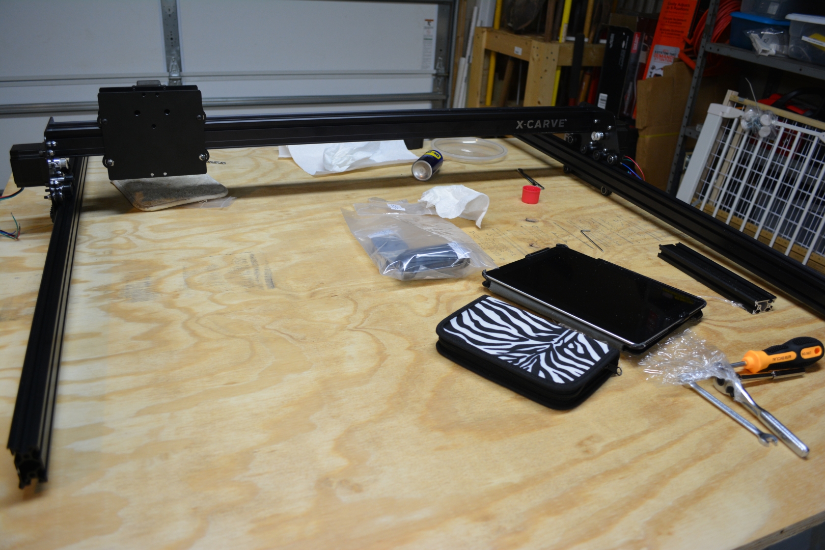
The Limit Switches - 1 Hour:
We took off one of the Y-Plates and slid off the X-Carriage. We were able to attach the limit switch, but in the process, we lost one of our M2 nuts. This brings me to a huge issue we have run into, there are 0 spare parts and many of these parts are extremely tiny. We had to go buy an M2 nut before we could continue adding the Y-Plate Limit Switch. We were able to remount the Y-Plate to the gantry without any issues.
Day 3: 6 Hours
The Limit Switches: Part 2 - 2 1/2 Hours:
The Y-Plate Limit switch itself was not hard to put on and we were able to put it on without incident, but we had to drive to 4 different stores to get an M2 Nut, Shielded Security wire, and a few parts for basic stiffening mods.
The Drag Chain Clips - 1/2 Hour:
The drag chain clips were very easy to install, but it we felt like we were going to crack the clip trying to remove it from the chain.
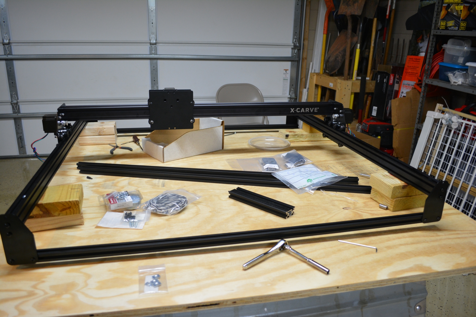
The Y-Axis - 1 Hour:
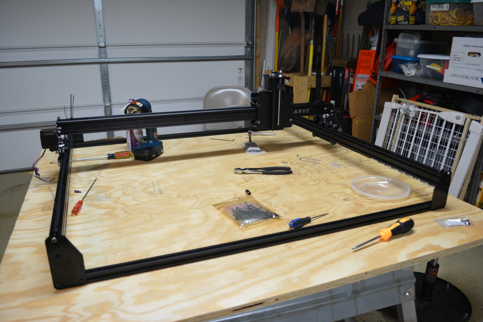
The Y-Axis end plates went on much smoother than the Gantry plates and we had little issue with them. We also started building the basic framework and now it is fairly rigid. There is some bowing in the gantry, but the stiffening mod should fix that.
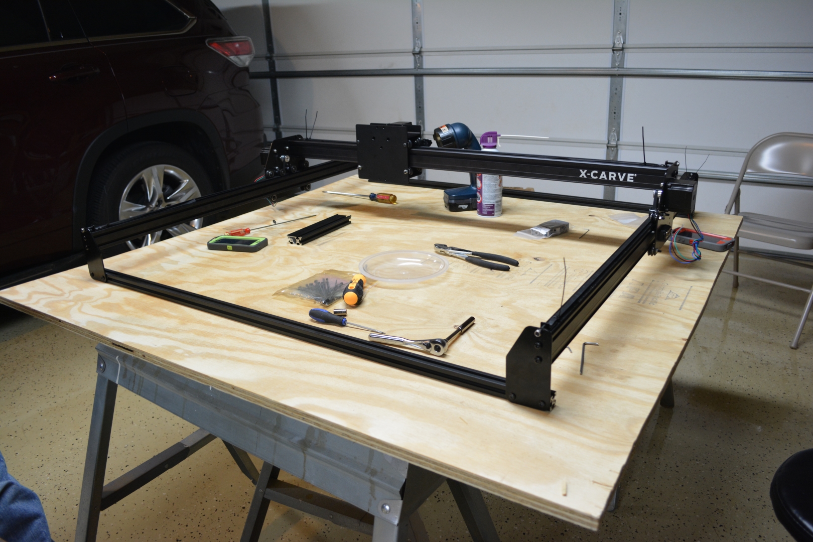
The Pulley Belts - 1 Hour:
The Pulley belts only took \~15-20 minutes, but we were at a standstill waiting for an answer to a question we had. The instructions do not say how long we had to cut the belts down to, so we had to post on the forums asking for help. We received a response in \~30-40 minutes. We used thin zip ties to lock the teeth into place and we got the belt tight while only having the nut flush with the end of the screw. This is to allow the belt to stretch, while still having enough of the screw to calibrate it once it has been broken in.
The Z-Axis - 1/2 Hour:
The Z-Axis went on very easily. The drive rod bearing was very easy to lock into place and the Maker Slide appeared to be pre-tapped, which made the thread forming screws basically slide on. The main issue with instructions at this step is they do not show a picture of the front of the X Carriage when you were sliding the Z-Axis assembly on, so it is very hard to tell how high up it needed to to be locked in. The Z-Axis limit switch was very easy to put on, with the whole Z-Plate acting as a nut for it.
The Drive Rod - 1/4 Hour:
The drive rod was probably the easiest part of this entire build so far, but it definitely is easier to do with 2 people. You have to hold the pulley in place, the rod in place, and screw in the set screw, without messing up the alignment of the pulley.
The Z-Motor - 1/4 Hour:
Putting the Z-Motor almost requires 2 people, not only do you have to line up the motor, you have to hold it in place, and tension the Closed Loop Z-Belt, while screwing it in. We tried to attach the motor first without the belt, like the instructions described, but we could not get it over either pulley. We had to put it on before hand and tension it while screwing it in.
Day 4: 5 1/4 Hours
“30 Minute Stiffening Mod” - 1/4 Hours:
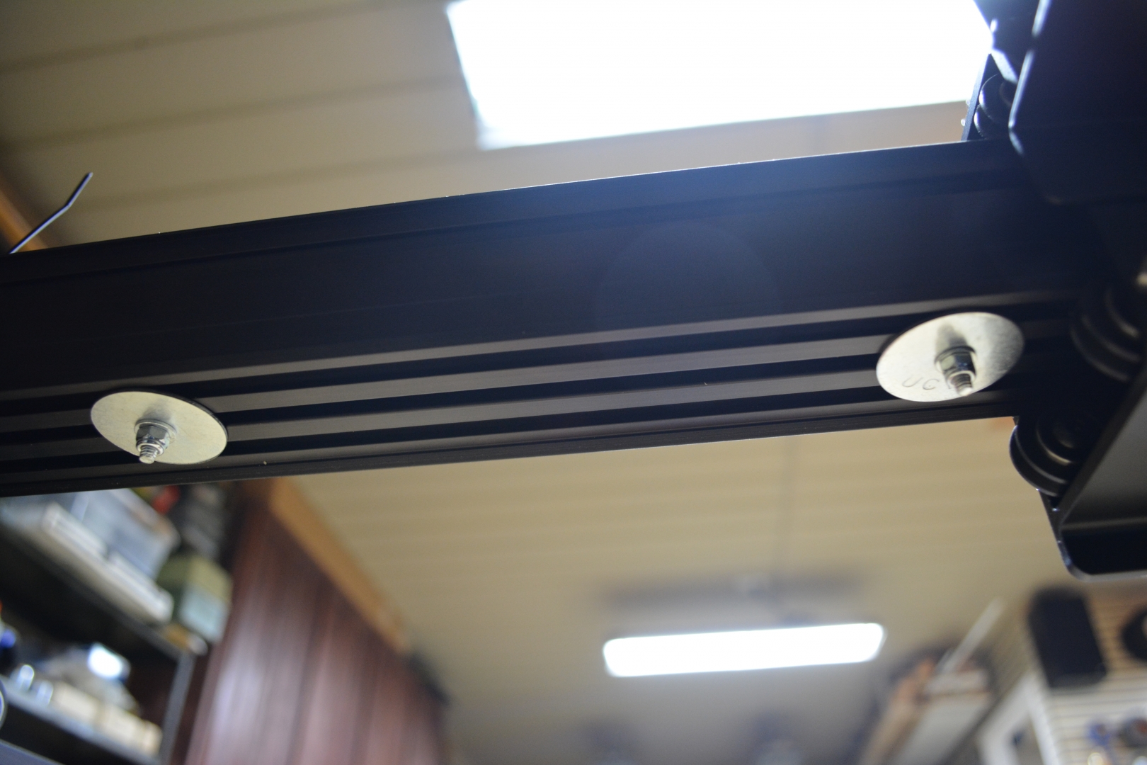
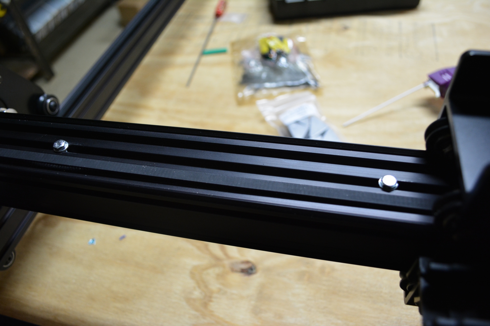
I used a variant of this stiffening mod using M4x50mm screws, flat washers, wide washers, and nylock nuts to stiffen the Gantry. Now there is no flex to it, but the X-Carriage is a bit harder to move by hand. We will probably end up fixing that during calibration.
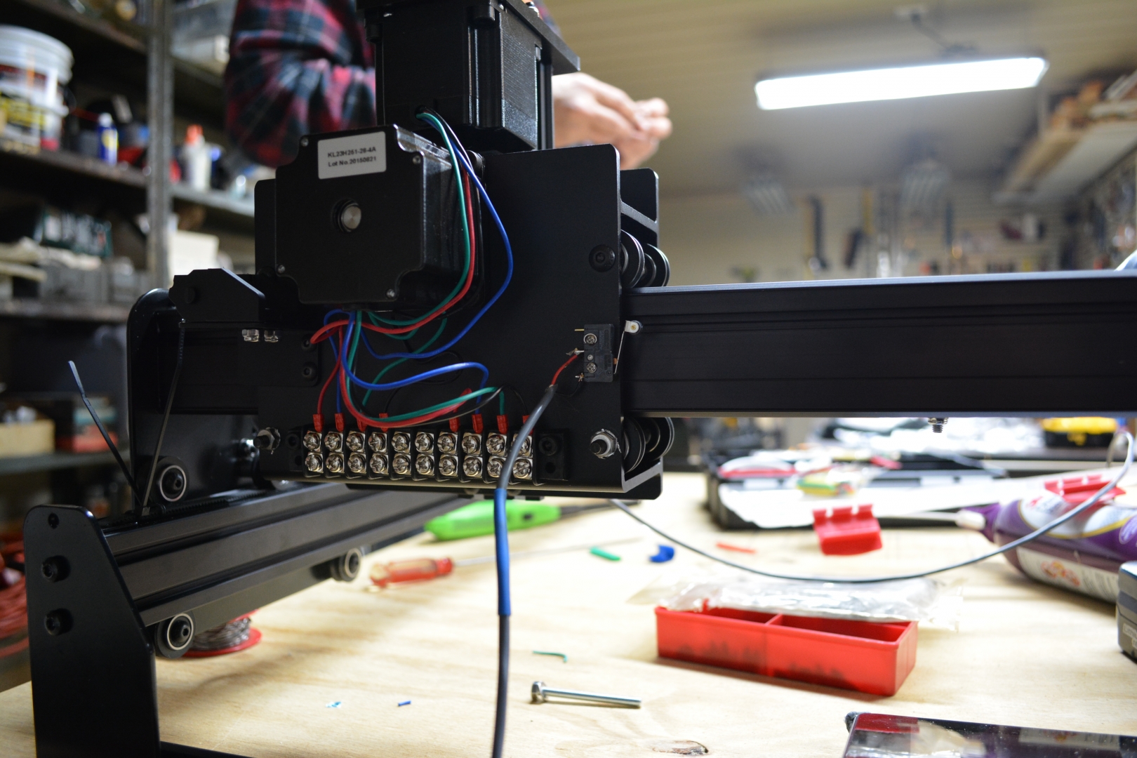
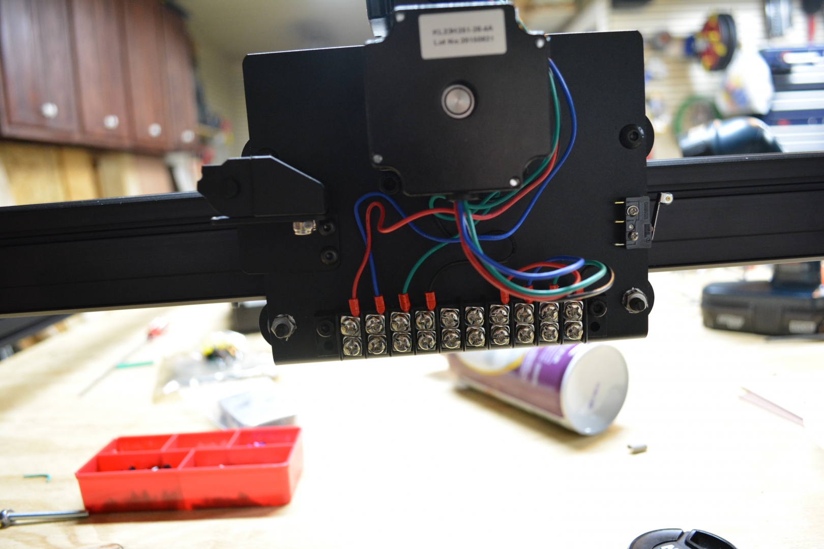
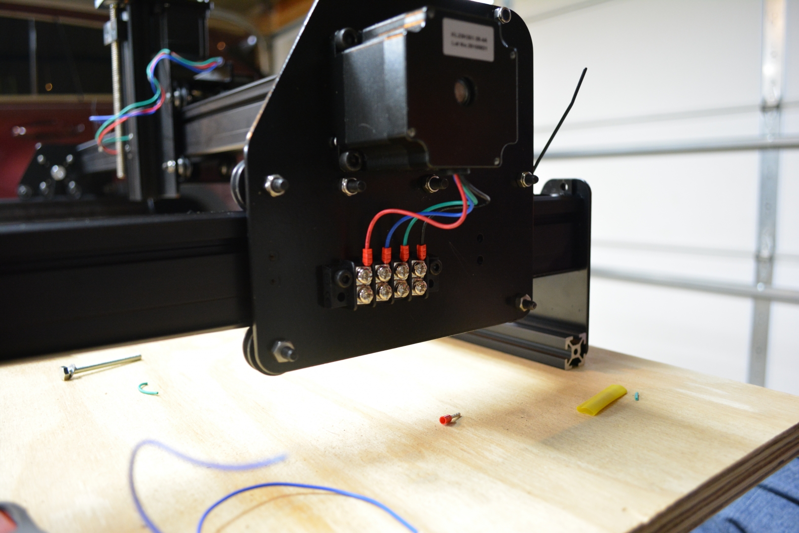
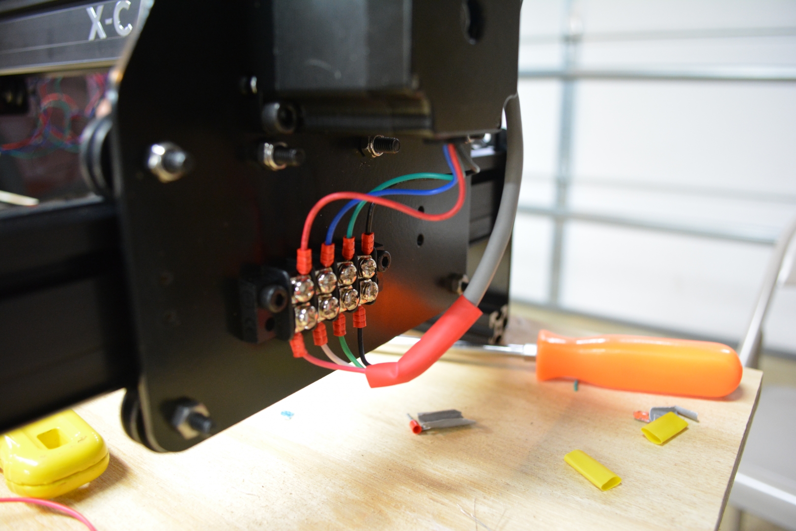
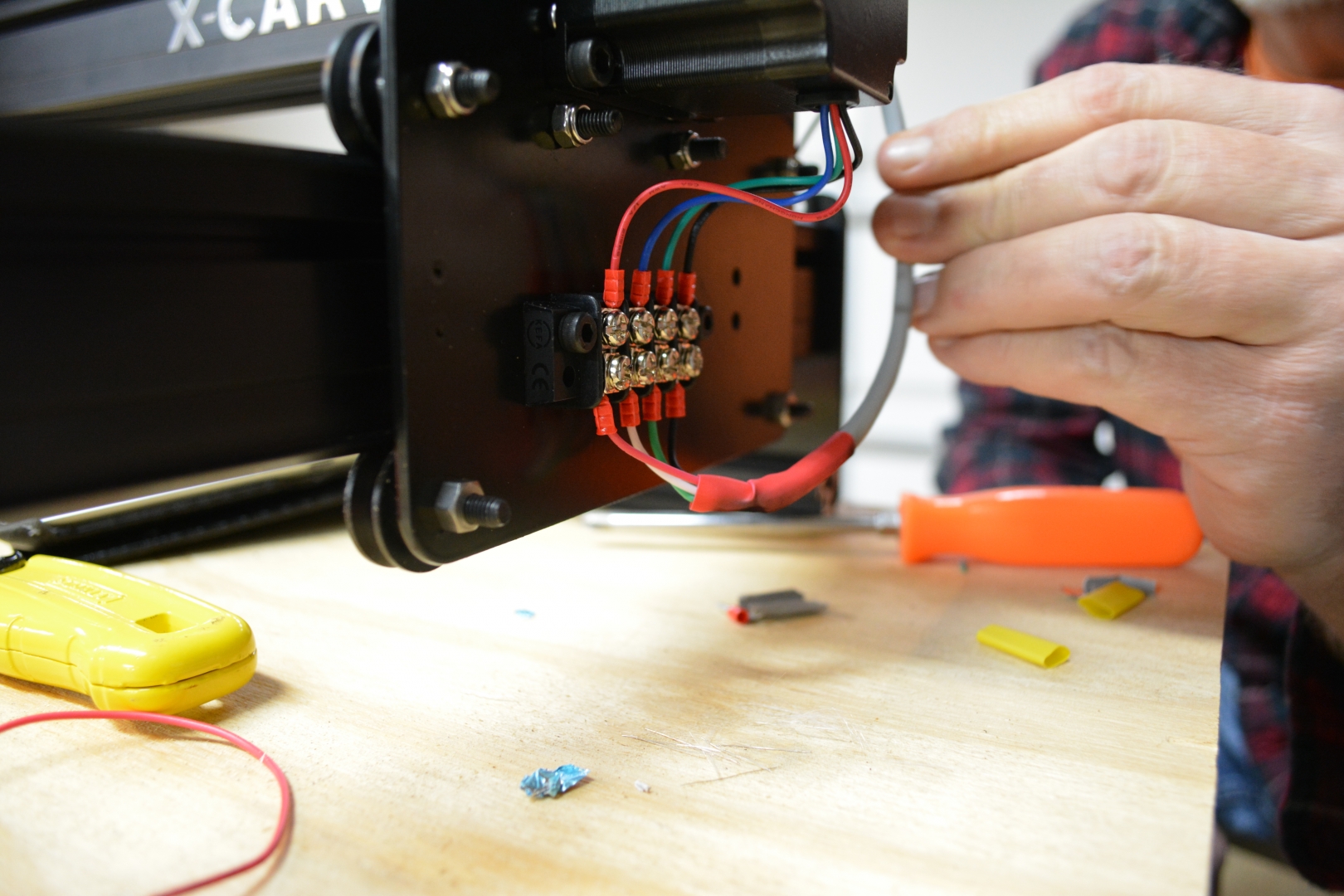
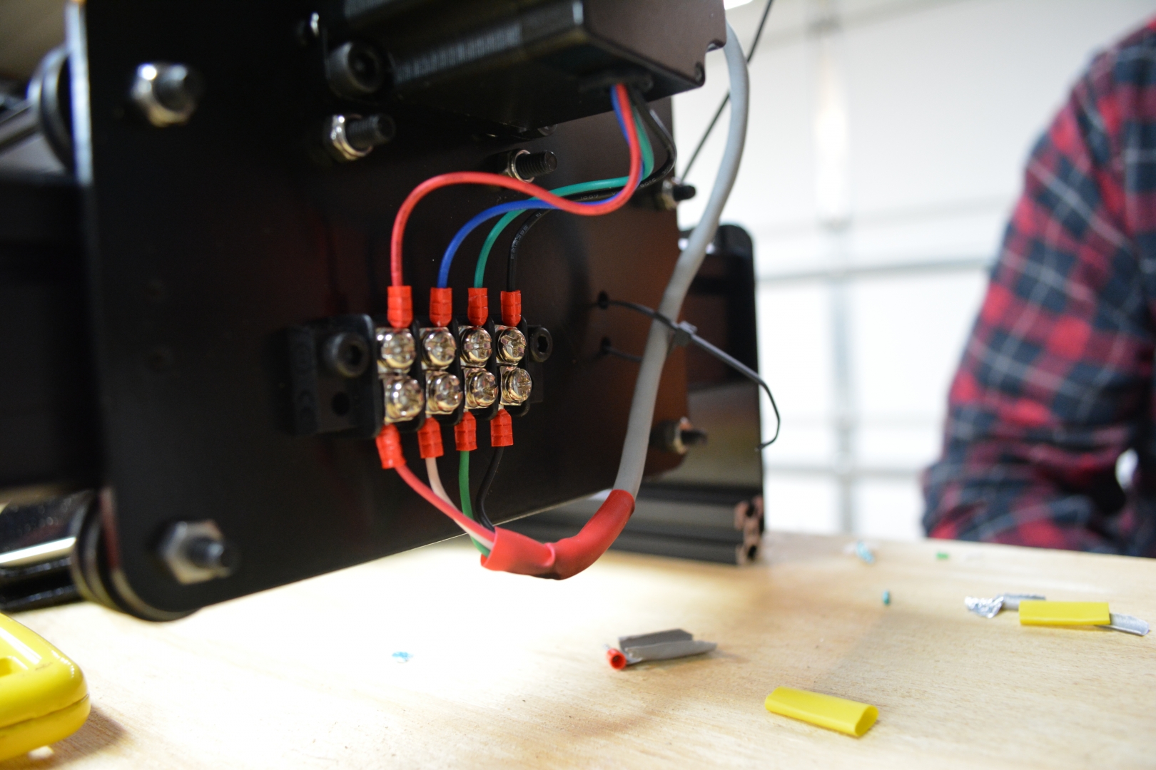
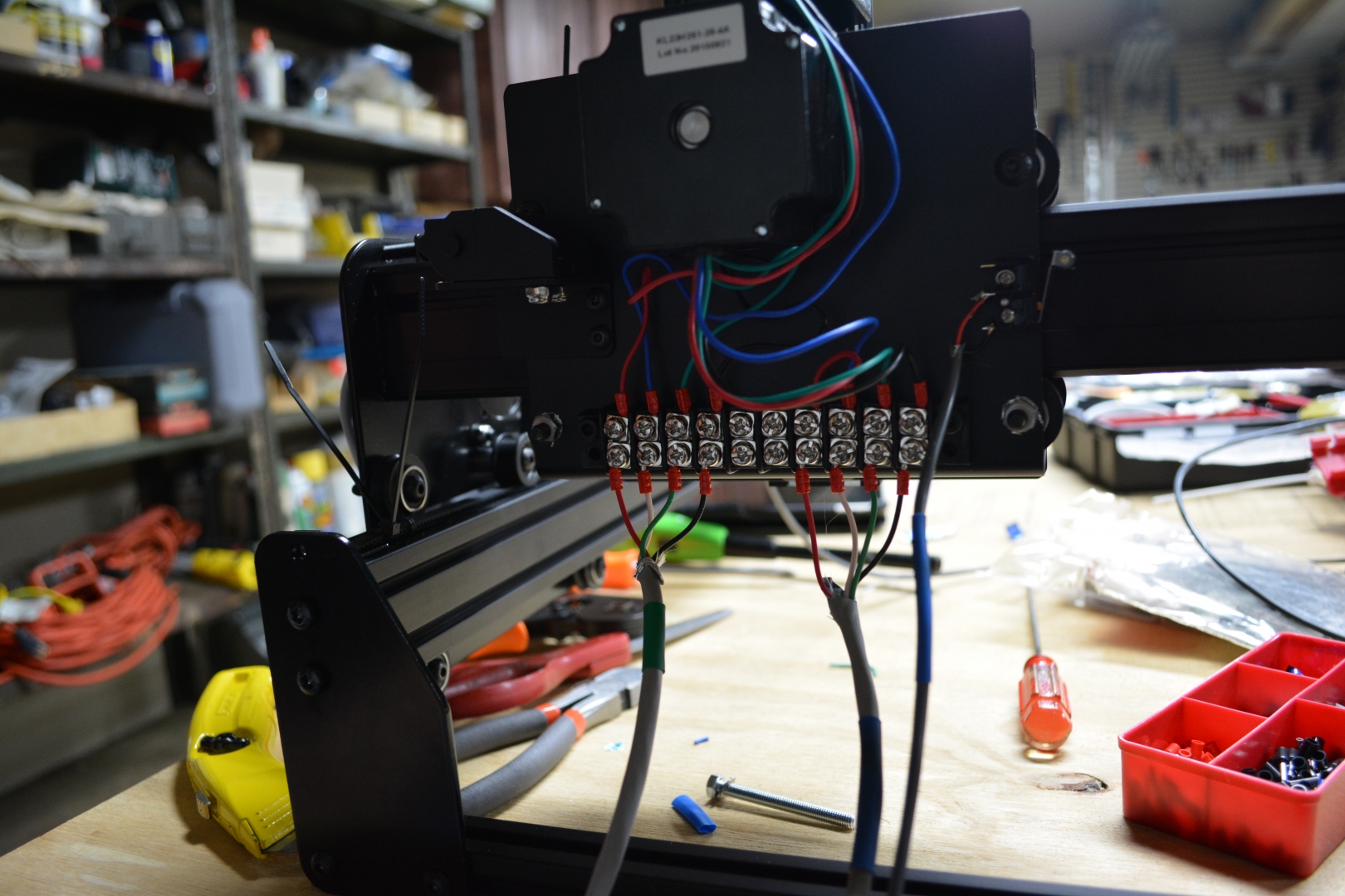
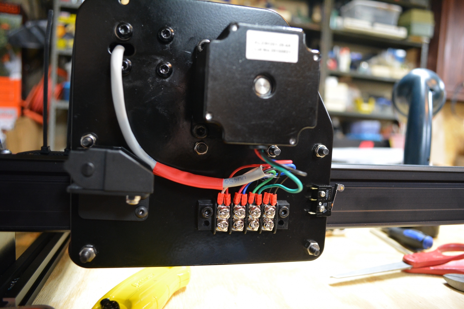
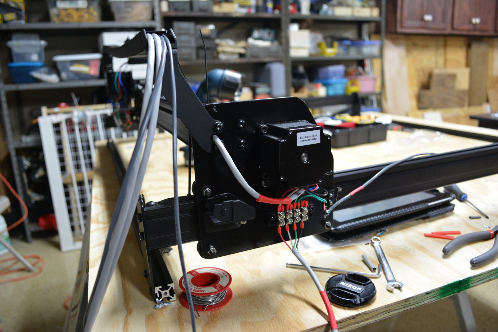
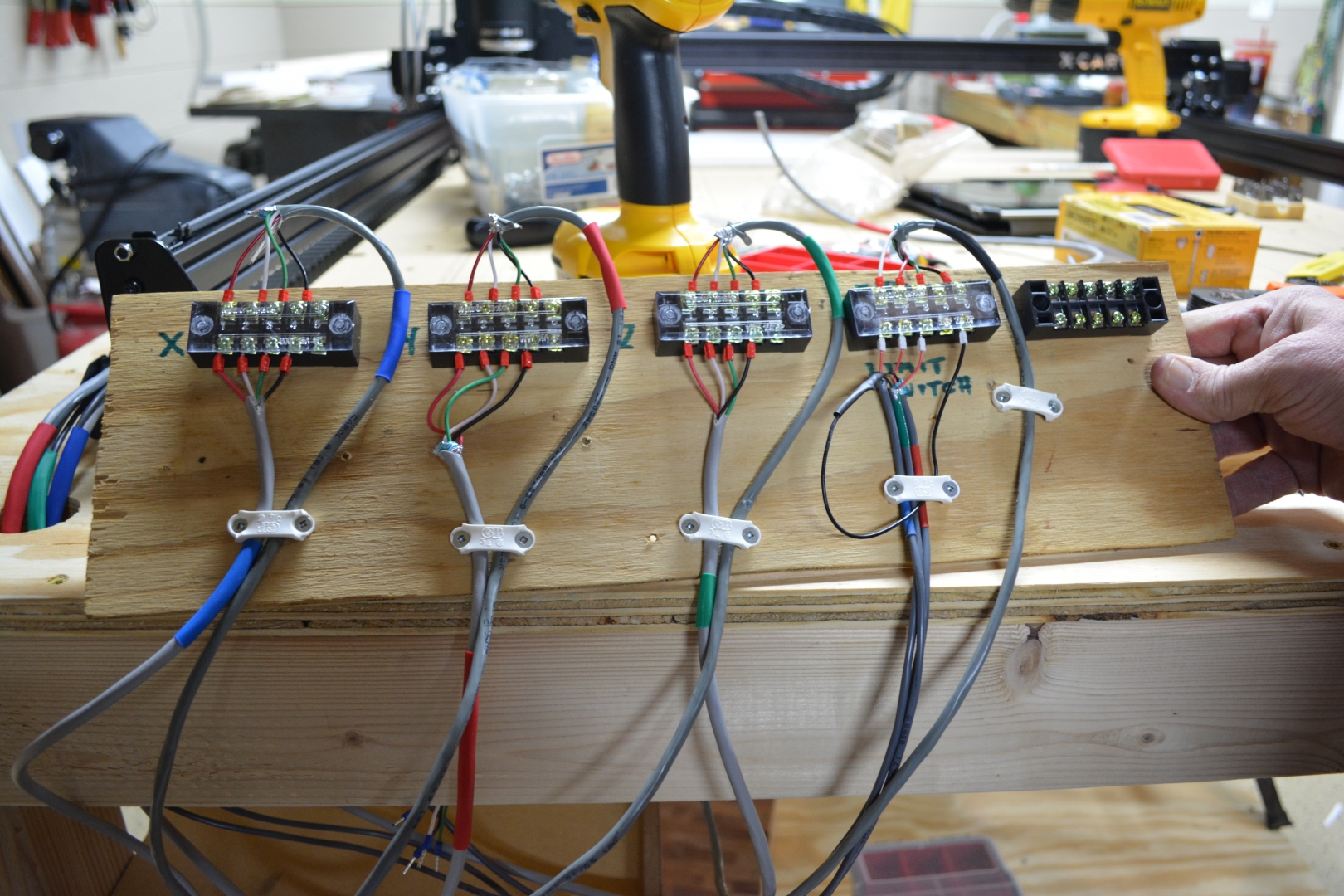
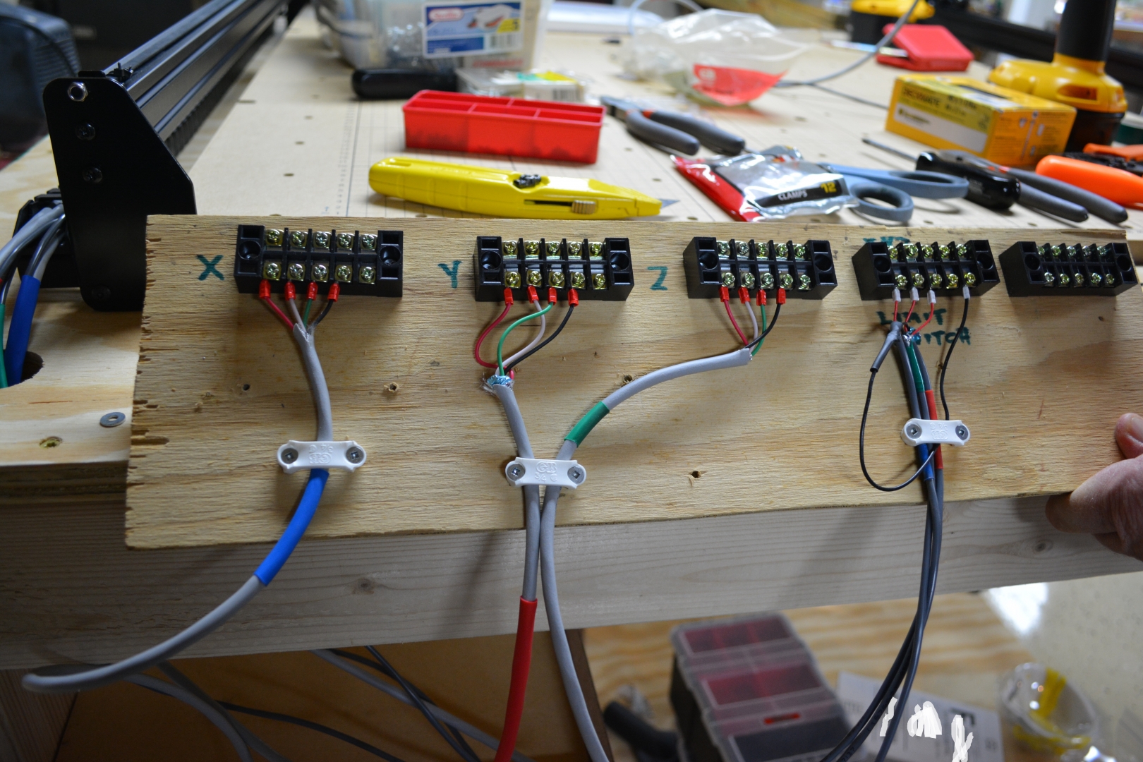
Wiring - 4 Hours : The wiring took a lot longer than expected, mainly because we had to add color coding to all the wires, ferrules to the ends of the wires, and strip & solder shielded wire for the Limit Switches. There were no real outstanding issues with wiring. just that it got a bit cramped under the motors, by the terminals. In the middle of soldering the limit switches, we had to make a run to Home Depot for more shielded wire because I did not get enough.
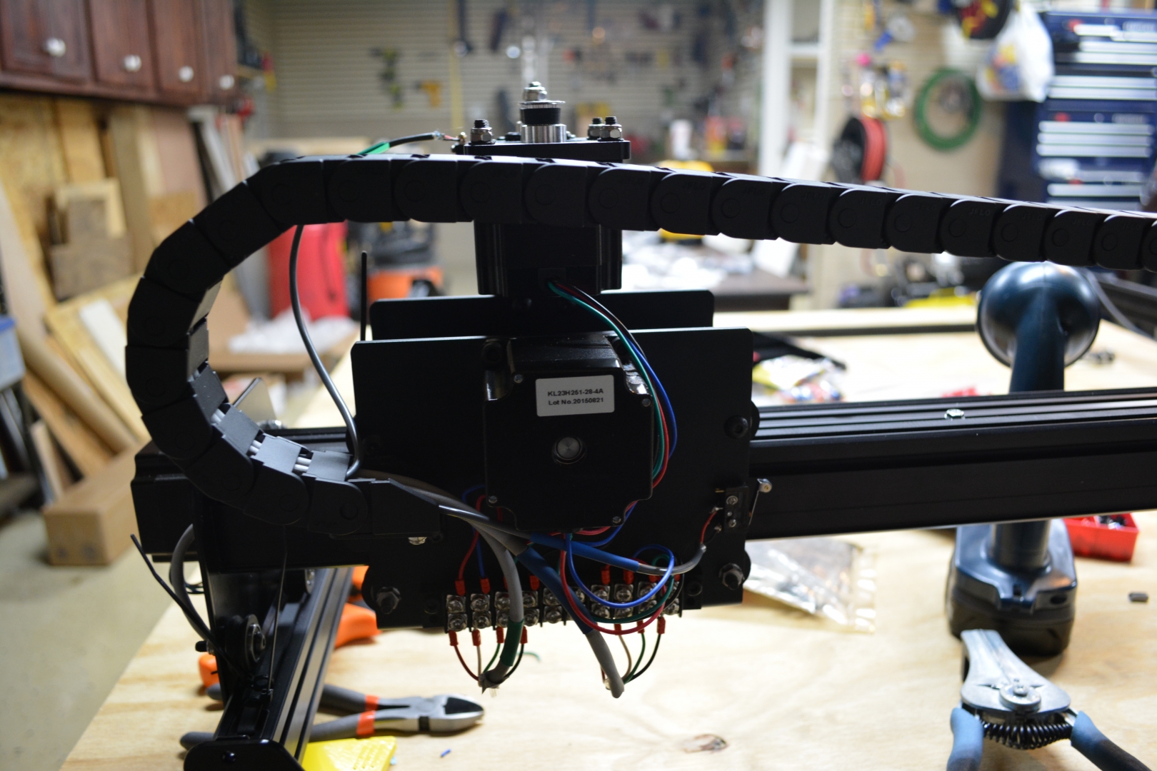
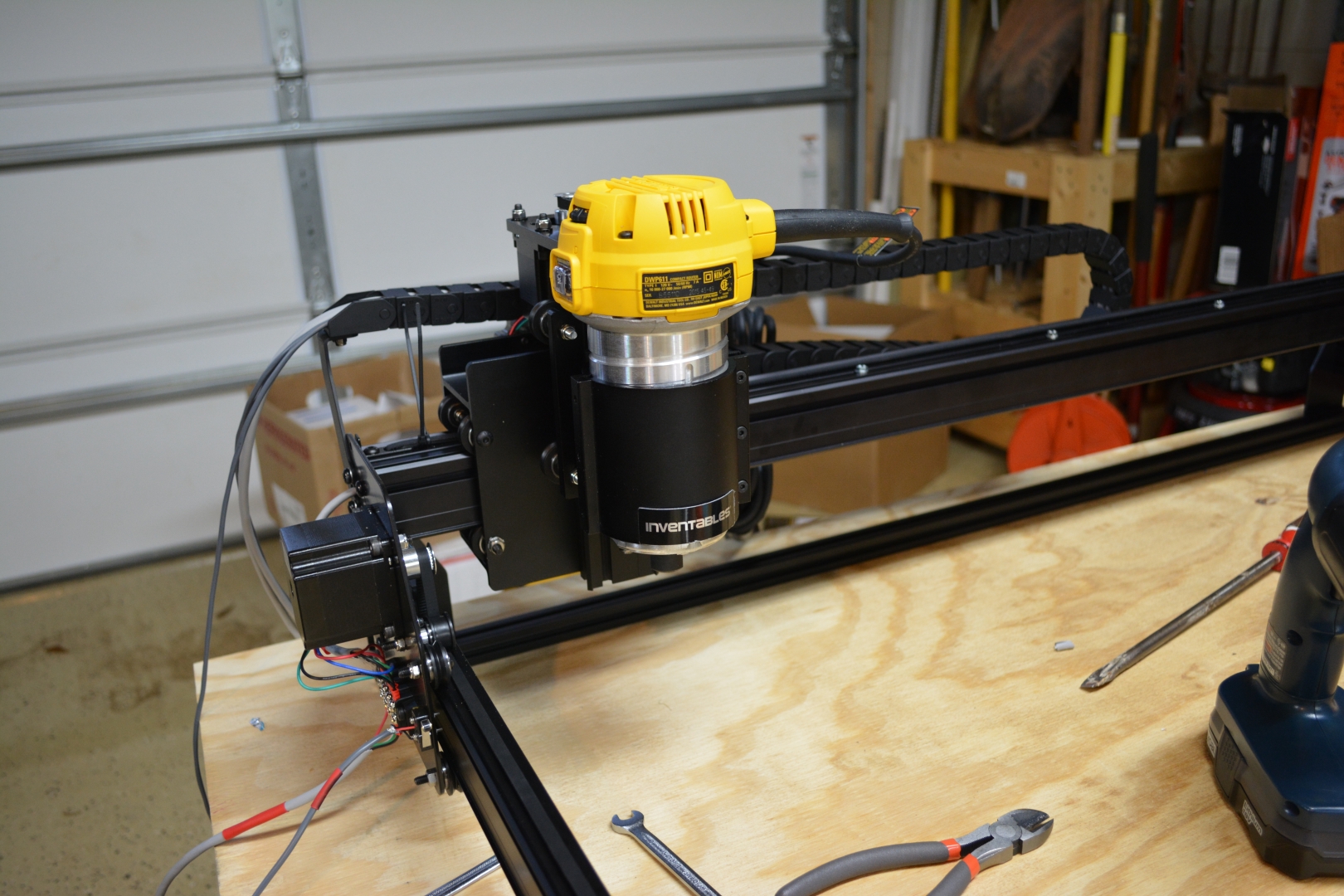
The Gantry Drag Chain - 1 Hour:
The Gantry Drag Chain was mostly easy to put on, with a few exceptions. You had to take off the female end, which does not have the specific tabs for removal or reconnection, so it felt like you were going to snap it at every moment. A major issue is they have you remove the 2 of the self tapping screws in the MakerSlide so you can put on the drag chain mounting bracket. This makes you run the risk of breaking a screw head while removing or adding it.

Day 5: 5 3/4 Hours
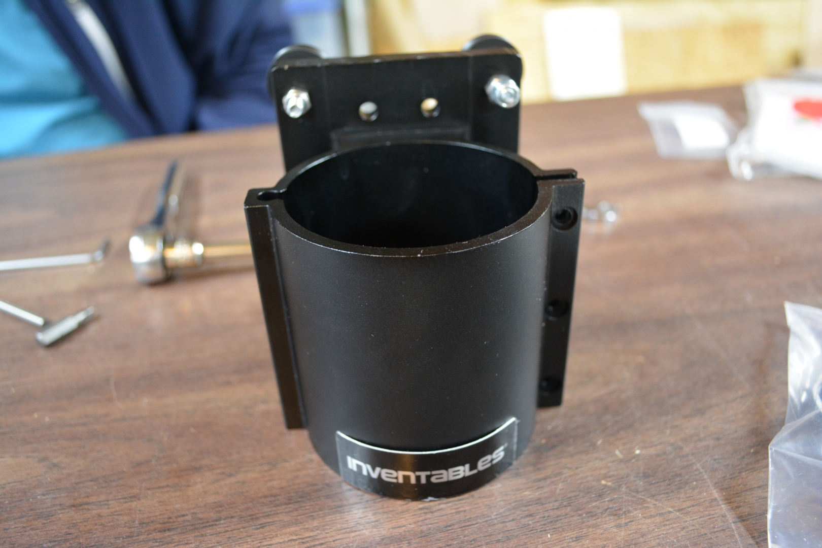
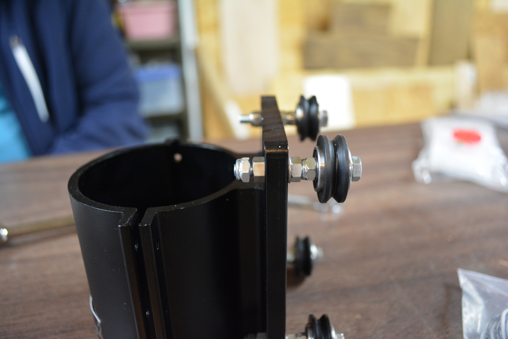
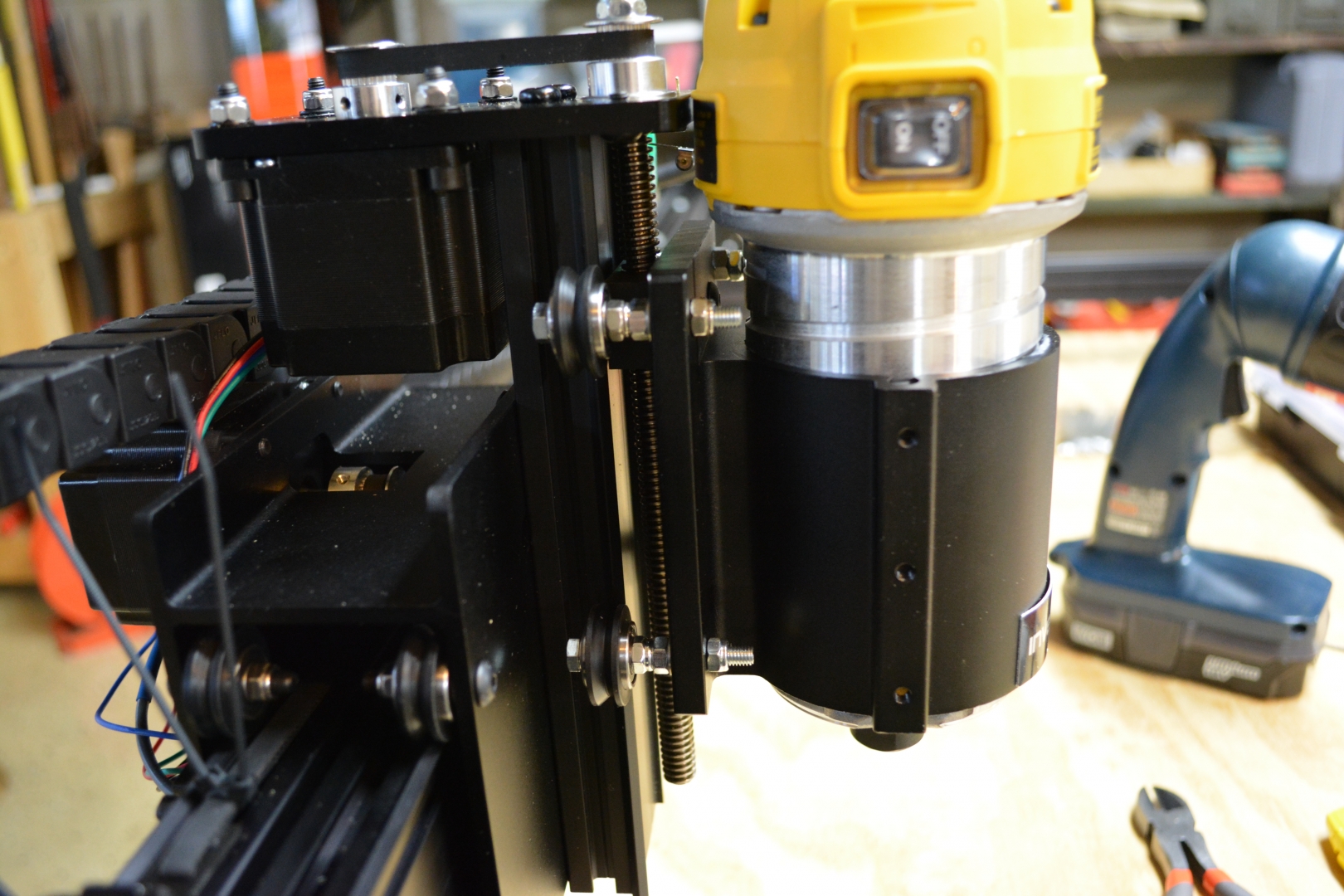
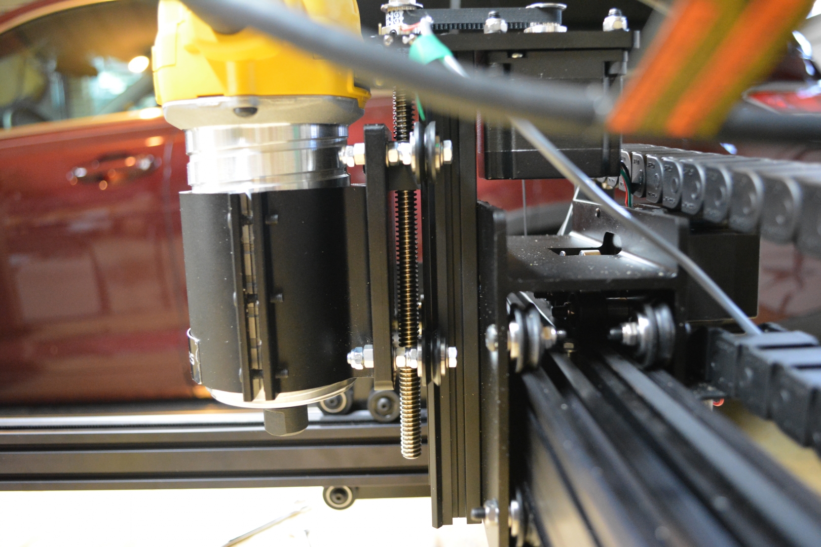
Spindle Mount - 3/4 Hour:
I used a variant of this Z-Axis stiffening mod using M5x40mm screws, flat washers, hex nuts, eccentric nuts, and nylock nuts to lock the V-Wheels in place and make them easier to adjust. The order is Screw, Washer, V-Wheels, Nylock Nut, Hex Nut, Washer, Eccentric nut (only on the eccentric side), and another Nylock Nut. I tried using M5x50mm screws, but there was not a lot of clearance. The 30mm washers that were used in the original post do not work because the DeWalt Spindle plate is a few Millimeters thicker. The router is much easier to mount with 2 people, one to check the height and to hold it while the other clamps down the mount with screws. The top of the router housing has almost no clearance with the Z-Plate. It moves fine, but there is less than 1 Millimeter of space between them.

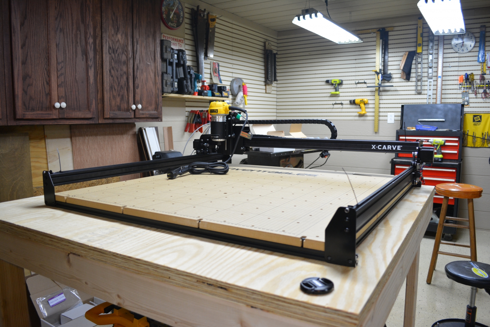
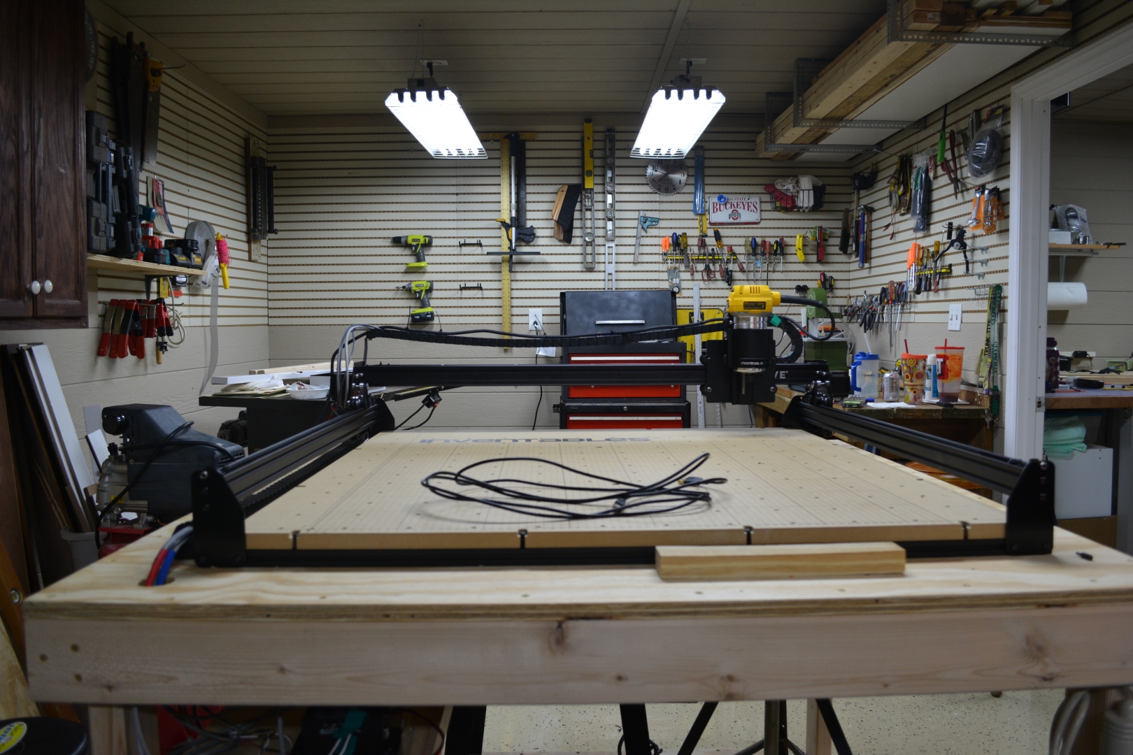
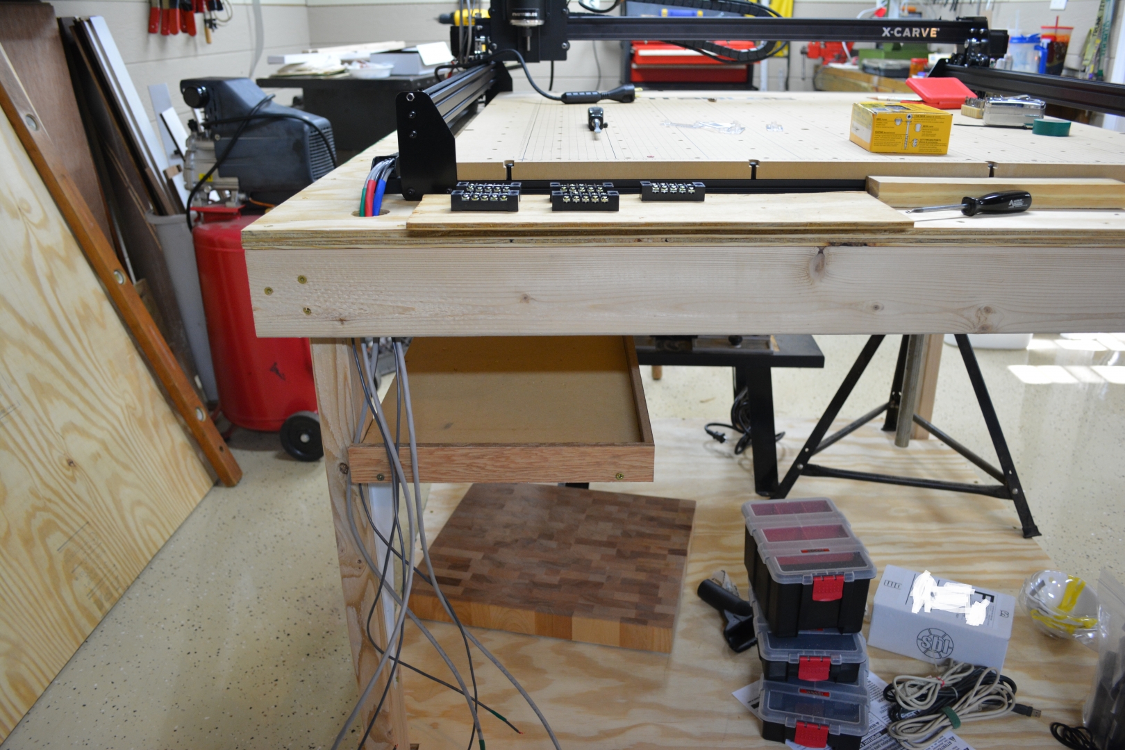
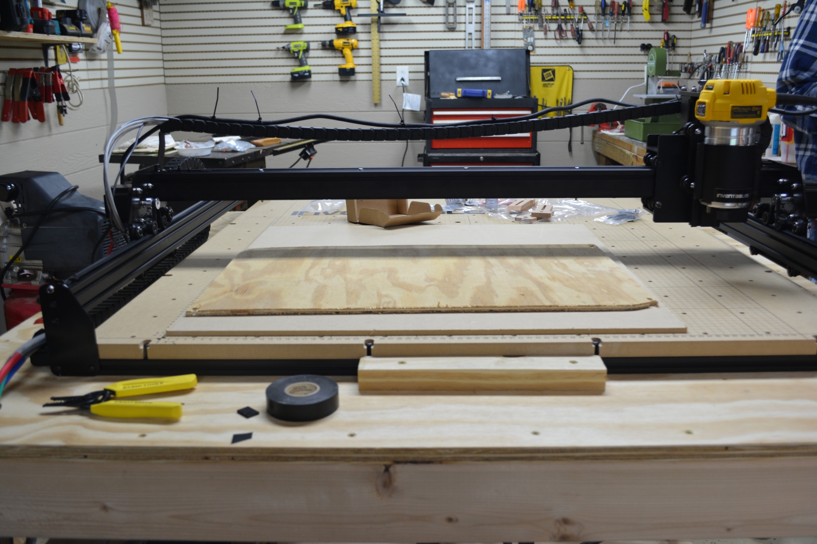
Work Area - 4 Hours :
The instructions for the work area caused a lot of problems. The instructions call for the extrusions that you mounted to the Y-Plates, however, the instructions have no mention of removing them from the frame and I was worried doing so would harm structural integrity. We called support, but we caught them in the middle of the meeting, so we turned to the forums for help. We waited about an hour and a half for a responses. In that time, we debated and put on the inserts on the back of the board. We managed to get the board mounted by mounting the center extrusion to the board and the outer 2 short extrusions loosely to the frame. We inserted all the preassembly nuts beforehand and we slid the board on at a tiny angle with the fulcrum on the back screws of the machine. We slid the front board mounting screws into place, carefully removed them, lowered the board into place, and reinserted them. We then aligned the side mounting screws and slid the extrusion inward until the screws were at the end of their respective holes. we tightened the screws down until the wasteboard was held firmly into place. With 4 people, we carefully lifted and moved the machine onto our rolling cart. By this point, the machine weighs 70+ pounds. We tightened the middle and the outside short extrusion brackets to the long extrusions by hanging \~6” off the edge of the cart and using the short side of the Allen wrench. We mounted the Y-Axis Drag Chain after feeding the X Axis, the Y-Axis, and the Z-Axis wire bundles through the chain. We ran into another issue with not having spare parts, we lost one of the screw to attach the female Drag Chain end, so we had to run to Home Depot to pick up the closes sized one. We mounted the DeWalt router cable to the Gantry Drag Chain using Zip-Ties. This did add a few pounds of weight to the drag chain, but otherwise there are no outstanding issues. The wasteboard itself was slightly damaged in shipping, a minor scuff/crack on the bottom of one of the mounting holes, but it was packed full of foam and bubble wrap, so it is not a packaging issue.
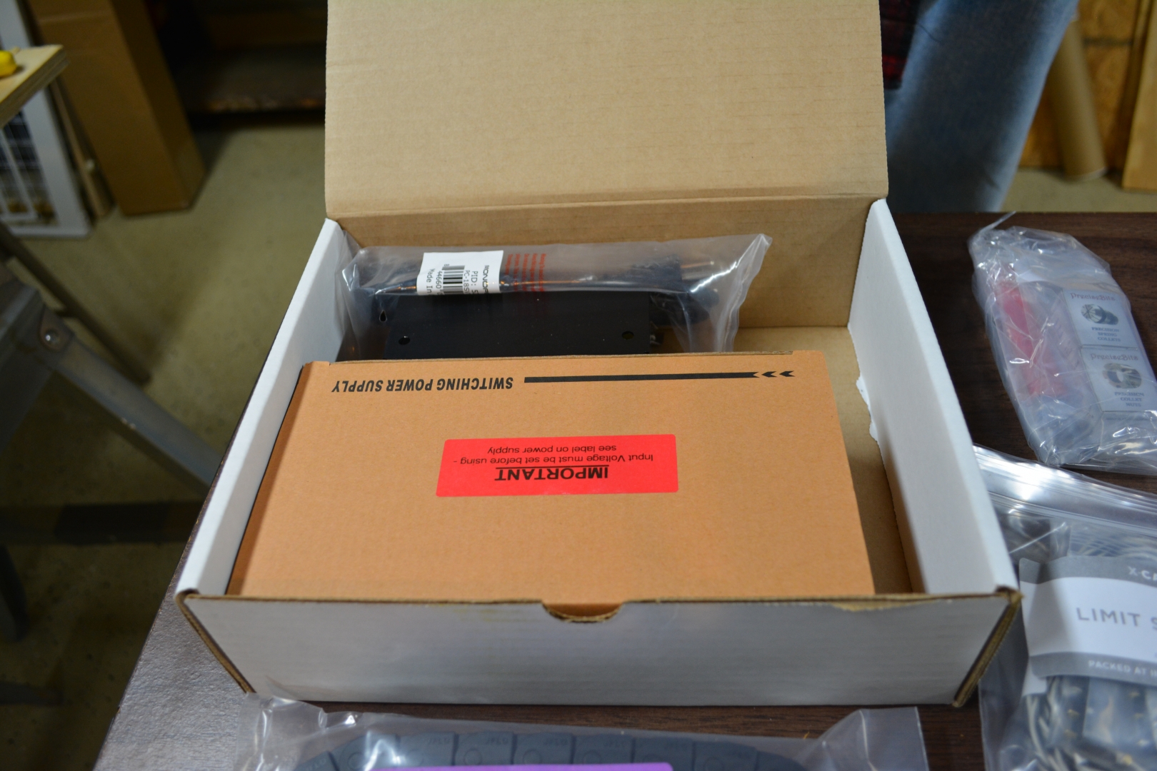
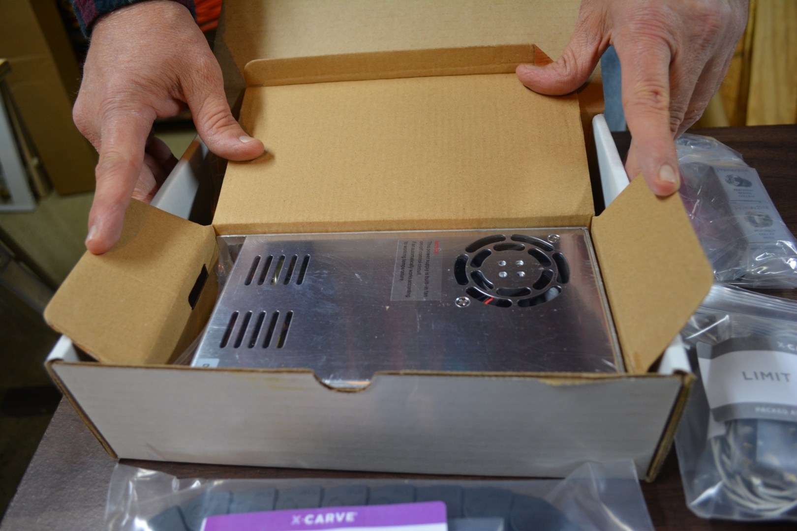
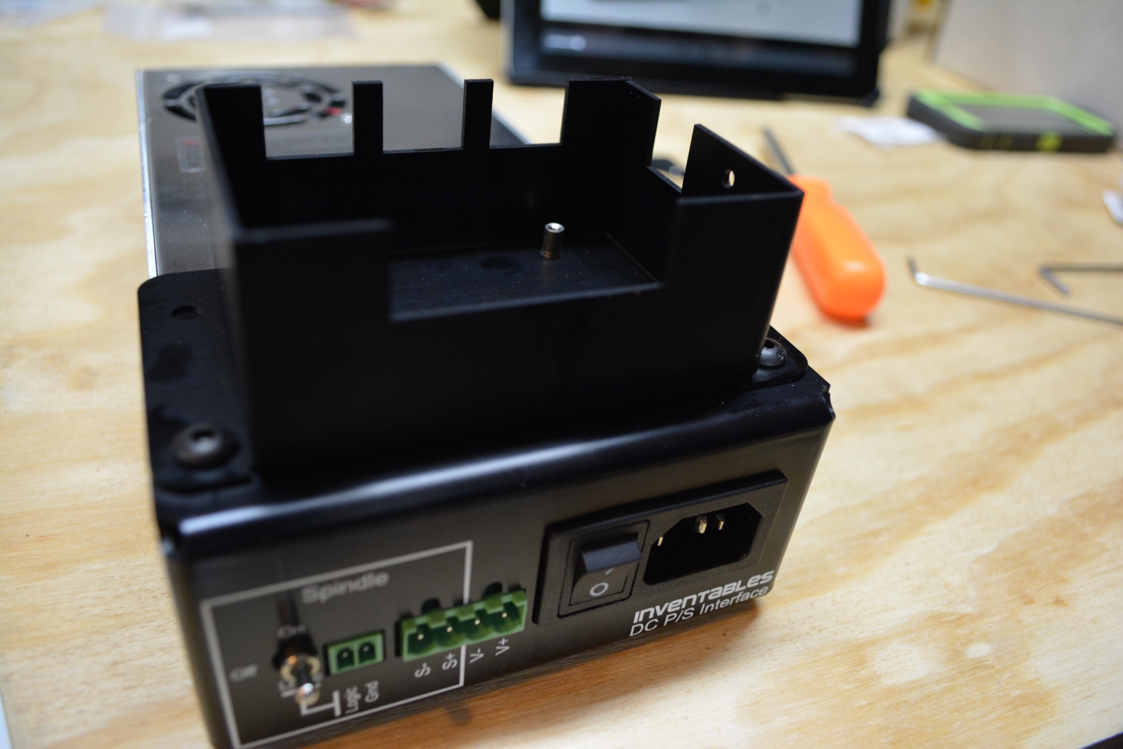
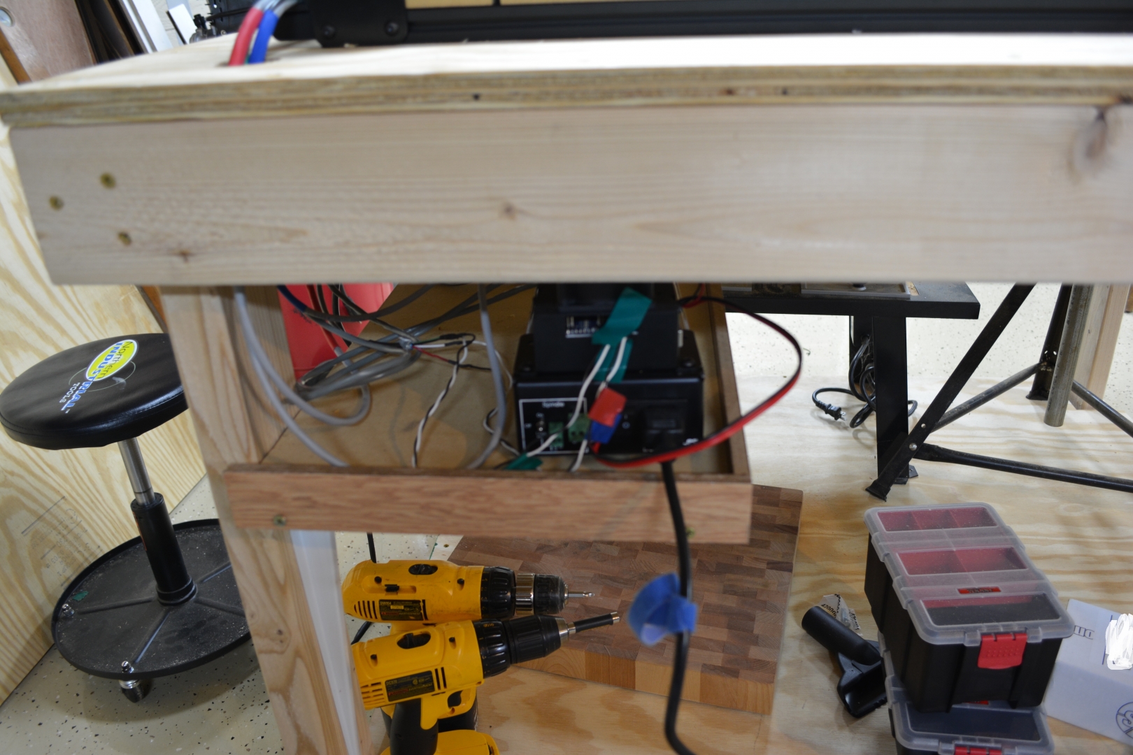
The Electronics: Part 1 - 1 Hour:
We did not do much to the electronics tonight, we just attached the interface, the case, and the Arduino board. The video for the electronics says to use nylon washers, but the written instructions say they are not needed.

Day 6: 8 1/4 Hours
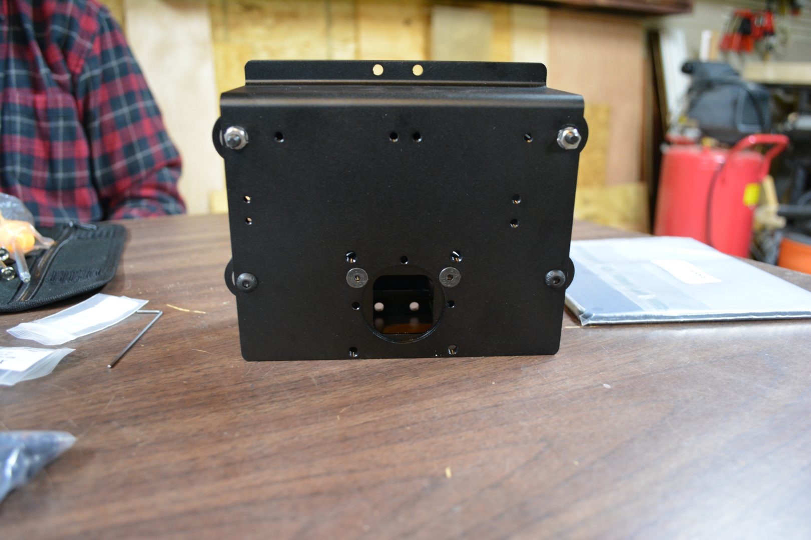
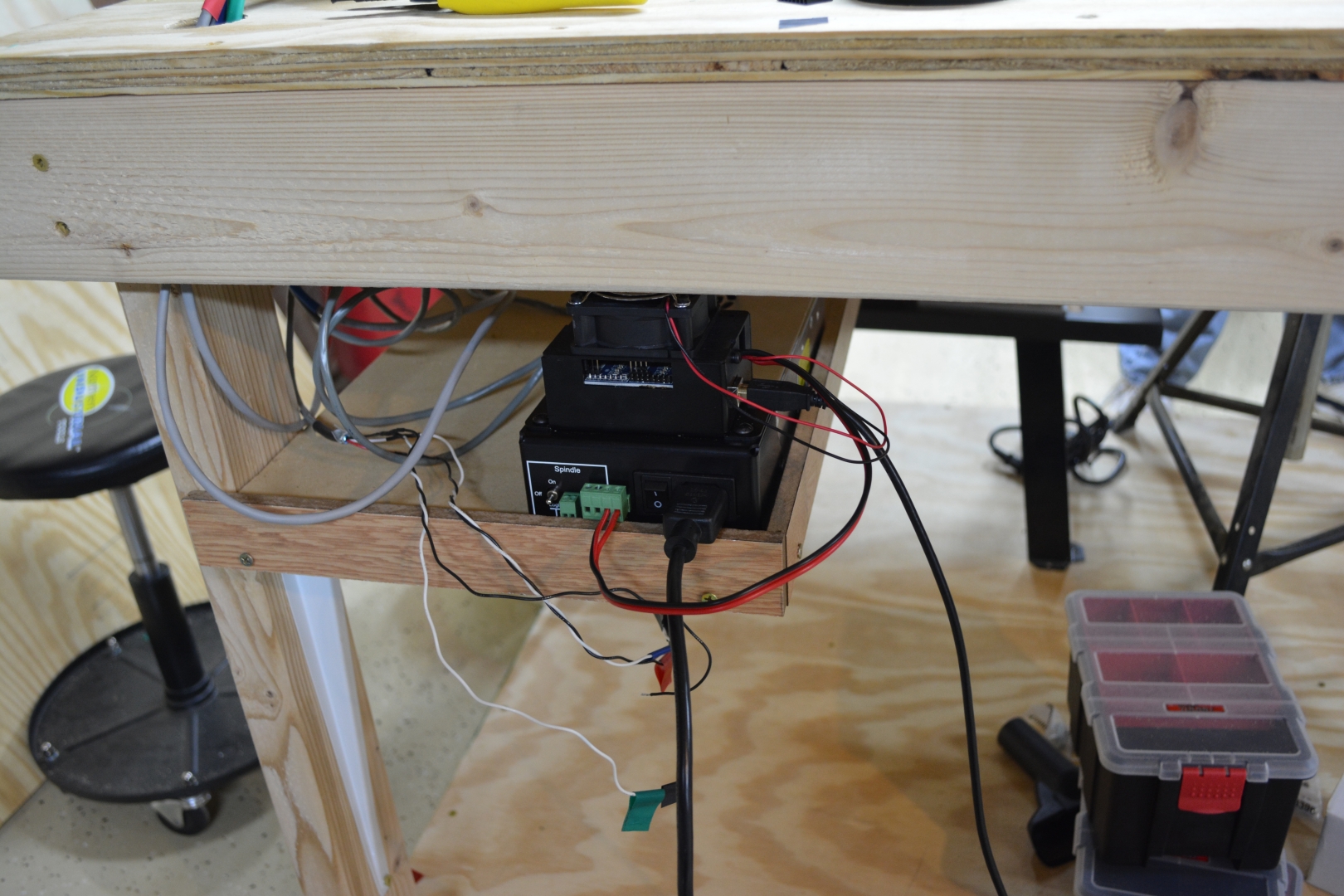
The Electronics: Part 2 - 7 Hours:
The electronics have arguably been the single longest part of constructing the X-Carve. One reason it took a long time is we had to attach terminal blocks to a board, strip 4 3’ shielded wires, attach ferrules to both ends and the ends of the stepper tables, and clamping the wires to the board. Soldering the connectors did not take long. The biggest issue we encountered was was connecting the wire clamps that went into the connector for limit switches. The clamps would not fit the wires inside the shielded cables, so we soldered some of the black and white wires to the ends of our shielded cable wires. We still encountered an issue where the clamps would not fit on the black and white wires and the connector were very loosely fitting. We started the machine, but my windows laptop was unable to even connect to the X-Carve. We eventually ended up using my brother’s Macbook Pro and were able to jog it.


Calibration Part 1 - 1 1/4 Hours:
While jogging the X-Axis, we realized that we Zip-Tied the cable to the drag chain the wrong way. The way we originally Zip-Tied it so it would pull on the cord as it moved down the gantry. We ran into an issue where the motor would not move the spindle above the halfway mount on the Z-Axis. Loosening the wheels helped, but we are still encountering the issue and the instructions say to tighten them so they can not be moved by your finger. We jogged the X-Axis and the Y-Axis. We noticed that the V-Wheels were hitting some of the Zip-Ties, so we had the ends facing the inside of the machine. In the end, we might end up using heat shrink once the belt finishes stretching.
Day 7: 6 3/4 Hours
Calibration Part 2 - 6 Hours:
We were able to track down the Z-Axis issue to the Stiffening mod we used on the Z-Axis. We remove the 2 nuts between the V-Wheels and the Spindle Plate and we replace them with the aluminum spacers. We also removed all the washers. after we did this, the Z-Axis moved without any issues. we did keep the Nylock nuts on the ends of the M-5x40mm screws just to help secure the eccentrics in place. We encountered issues getting the Limit Switches to work, but that was tracked down to 2 issues, the connector not fitting correctly and us wiring the ground into the connector like the diagram shows, but the ground in the connector is for the spindle control. Once we connected the Ground to the G-Shield ground, removed the clamps from the connector, and placed the clamps directly onto their corresponding spots, wrapping them with electrical tape, the limit switches partially work. They will stop the Z-Axis, but they do not continue to testing the other axis. After we came back from lunch, we were unable to jog the Z-Axis down, both buttons were jogged it up. after a reset, none of the Axis moved at all. we were able to track it down the the G-Shield being unmounted during fixing the limit switches. We ended up not activating the limit switches because we were still having issues with them.
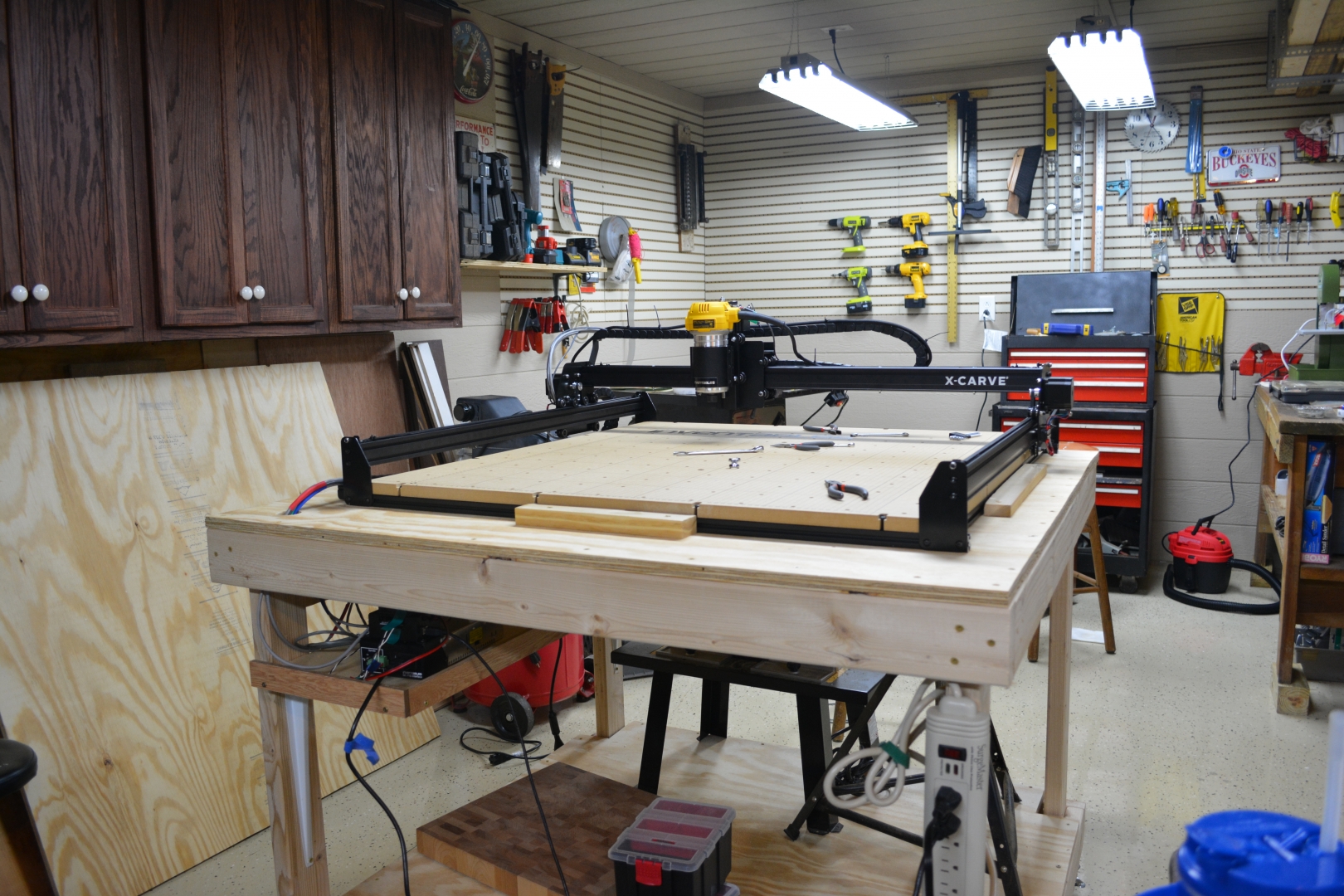
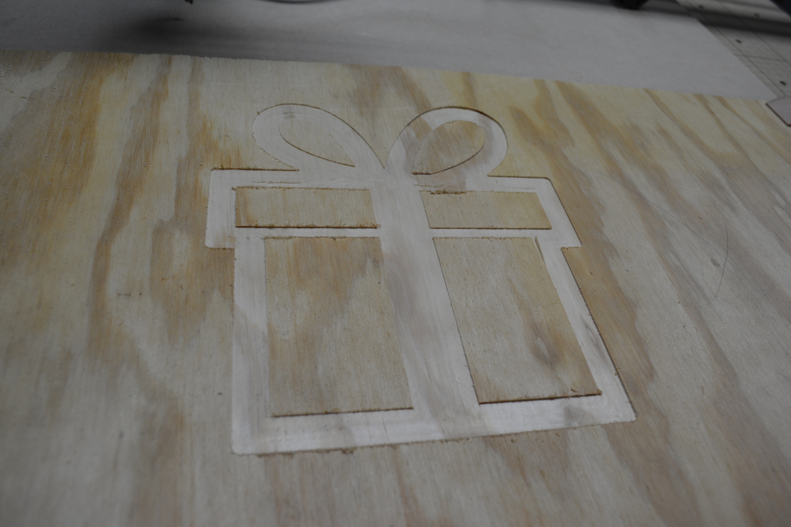
The First Cut - 3/4 Hour:
Using a 1/4” High Speed 2-Flute bit, we cut a gift box with a bow into a sheet of pine plywood. We had to use the Macbook b/c we still have not figured out how to fix the Windows problem. The cut is very clean, aside from some splintering. I did hear some chattering. The cut only took about 7 minutes, but we had to arrange our secondary wasteboard, clamp down the plywood to it, design the carve file, and check all the electronics.
Final Thoughts - 39 1/2 Hours Total
The Good:
- The machine is very well built, sturdy, and everything fit snugly.
- For an uncalibrated first cut, it cut very cleanly.
- The machine itself did not require a lot of finicky calibration after building
The Bad:
- The Machine comes with almost no spare parts to speak of, especially no spare parts for the tiny nuts and screws.
- The Limit Switch Connectors don’t seem to snugly fit the supplied wires and G-Shield Pins.
- The instructions are woefully vague and the pictures are taken at weird angles[[
]{style=”text-decoration: underline;”}]{style=”text-decoration: underline;”}
Parting Tips:
- You can buy most screws, nuts, bolts, and parts at Home Depot and ACE Hardware.
- Some people refer to security cable as in-wall speaker wire.
- place your zip-ties as close as you can to the Y-Plates because the Smooth-Idlers can hit them.
Disclaimers: I DID NOT receive a free X-Carve From Inventables. This review is based on the Version available on 11/27/15.